Parts identification, Wing assembly, Using this instruction manual – Carl Goldberg GBGA1040 User Manual
Page 3: Preparing for assembly, Construction tips
3
Using This Instruction Manual
Before you start gluing take some time to look through this entire
instruction booklet. It is designed to guide you through the con-
struction process step by step, so build in the order given in this
book. Radio selection and installation , balancing and flying the
model are all covered.
Like a full-size airplane, the Electra ARF is built from basic
structures (stabilizer, fin, wing, etc.), which are then assembled
into the complete airplane.
Special procedures or comments will usually be explained before
a step, so you will be prepared. If a step begins with a statement
like “Note,” “Warning,” or “Important,” it is a good idea to read
through the step before doing it.
A check-off box appears at the beginning of each step. Check
these boxes as you build, so you can tell at a glance what steps you
have completed.
Some of the instructions deal with general procedures. Boxes are
not needed for these sections.
Preparing For Assembly
You will need a area approximately 18” x 80” in order to build
the Electra ARF. Place a sheet of waxed paper or plastic kitchen
wrap over the work area to prevent CA from sticking to your table.
Construction Tips
If you have never assembled a built-up model before, the follow-
ing tips will prove helpful.
IMPORTANT: ALWAYS READ A FEW STEPS AHEAD. This
will alert you to coming instructions and will help you plan
accordingly.
You may find it convenient to empty all of the small parts from
the hardware bags into a common container, such as a margarine
tub. This will help you find items quickly.
When drilling any 1/16” holes in balsa, you may find it easier to
twist the drill between your thumb and index finger. This proce-
dure allows more control in positioning the drill on the center
mark.
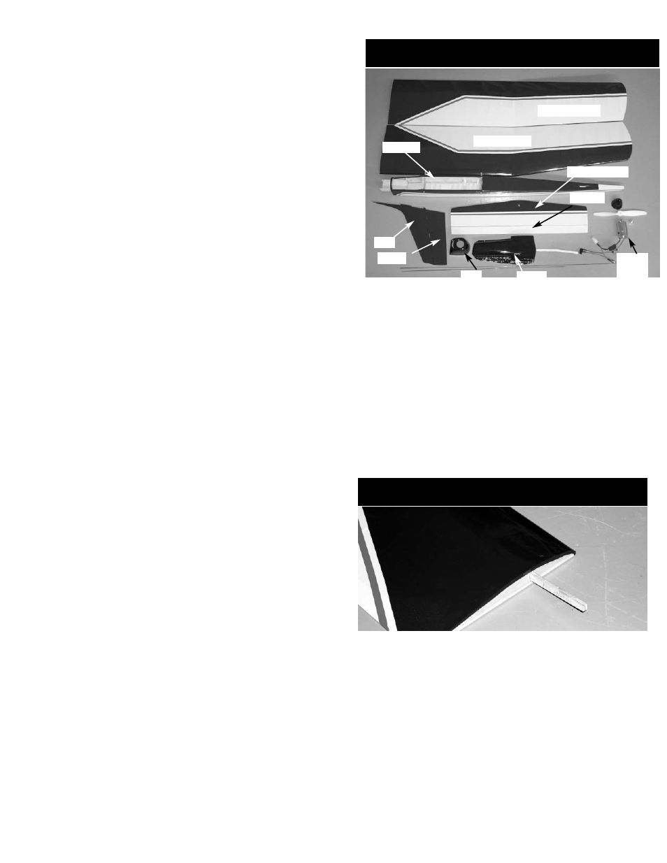
Parts Identification
Stabilizer (Stab)
Left Wing Panel
Fin
Fuselage
Rudder
Right Wing Panel
Elevator
Additional Items included in the kit:
(2) Control Horns
(2) Control Horn Bases
(4) 2-56 x 1/2” Pan Head Screw
(2) Wire
(2) Snap Links
(2) Snap Link Retainers
(2) Pushrod Connectors
(1) Wood wing Joiner
(1) Prop hub assembly
Wing Assembly
1.
Collect the following parts:
(1) Left wing panel
(1) Right wing panel
(1) Wing Joiner
2.
Holding the wing joiner with the angle cut facing up,
insert them into the joiner pockets in both wing
halves. The joiners should fit easily in the pockets
and the wing halves should meet in the middle, with
the wing dihedral forming a broad "V".
3.
Working on a protected surface, and with a paper
towel handy for cleaning fingers, THOROUGHLY
mix 1-2 large (soup) spoons each from bottle A and
bottle B of epoxy. (Use equal amount of each part
and mix with a stick in a plastic or paper cup, or on
a sheet of waxed paper.)
Cowl
Canopy
Motor
Prop
Spinner