Carl Goldberg GPMA0963 Cub User Manual
Page 27
26
VI PREPARATION AND INSTALLATION OF RADIO
Model is fully covered and painted wherever
necessary (Page 22).
Control surfaces are covered, and hinged in place (Page 23).
Tail assembly is glued solidly to fuse (Page23).
Engine screwed in place (Page 14).
Muffler on.
Prop in place.
Fuel tank installed, with foam rubber supports to hold it level.
Stab and rudder pushrods complete, rear end only (Page 14).
Landing gear and wheels installed.
2. BALANCING THE MODEL
Tape stab and rudder pushrods to side of fuse with rear ends in
approximate final position (refer to full size view on plan).
Set R/C airborne equipment temporarily in fuse (refer to plan for
approximate location).
a) Battery most forward.
b)Receiver (RX) next.
c)Servos rearmost.
d) Install aileron servo in wing.
Refer to fuse side view on plan for “BALANCE RANGE,” then
measure and mark this range at top of cabin sides.
Bolt wing in place on top of fuse.
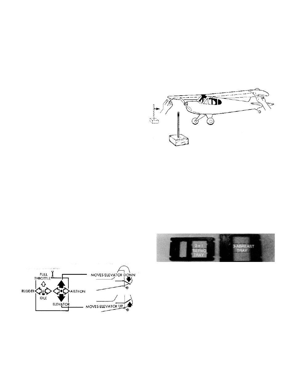
Enlist someone’s aid to help you balance the model as shown.
If you must balance it alone, make the simple balance stand at left
from scrap lumber (2x4, etc.) to assist you Lift the model under the
wing by finger tips.
a) Move finger tips or balance stand through the balance range until
model is level.
b) If you need to support the model outside the balance range to
get it level, remove wing and shift R/C equipment away from heavy
end of model until model will balance within the range. The pre
ferred location is at the main wing spar.
c) If shifting the R/C gear still doesn’t balance the model, add
weight to extreme nose or tail respectively until it’s right. The least
weight is needed when added as far forward.or back as possible.
Fasten weight permanently in place.
Carefully remove the wing, and mark on fuse interior
the locations of all R/C parts.
Completing elevator and rudder pushrods.
a) Measure about 2” from the backsides of the servos to
the balsa pushrods, and mark them at this point.
b) Remove pushrods from fuse, and cut them at marks.
c) Cut one 1/16” x12” wire in half, and use these pieces
to complete forward end of pushrods.
3. Radio installation.
A. Read and follow the instructions that come with your radio.
B. Your batteries should be fully charged.
C. Refer to “Transmitter Function Sketch” and observe which servo
wheels move when stick is moved for various controls.
Apply tape (which you can write on) to each servo. Identify each servo
for its control function. Mark the plug to each servo the same way: “R” for
rudder, “E” for elevator, “T” for throttle, “A” for ailerons. If your receiver
doesn’t have separate plugs for each servo, but places for the servos to plug in,
apply a piece of tape nearby that you can mark for each application.
If a servo mounting tray is furnished with your radio, it
makes it easier to mount servos. The most common tray
is a “2+1” type (as shown above left and in the main
plan view).Either a 2+1 or a 3-abreast can be used in the
CUB because of its wide roomy interior. Note: if a tray
is not used, the 3-abreast mounting is recommended with
servos mounted directly on plywood rails (as shown
below the main plan view).
For “2+1” mounting, with throttle servo at forward posi-
tion, place servo so output wheel is on same side as engine
throttle arm. For 3-abreast mounting, place throttle servo on
same side of model as throttle arm.
Rudder servo should be on side opposite to throttle servo.
4. Servo arrangement.