Carl Goldberg GPMA0963 Cub User Manual
Page 24
23
COVERING THE FUSELAGE 1. For added realism, the cabin interior may be painted: this is easily done now, before
covering, using spray paint such as gray auto primer.
2.
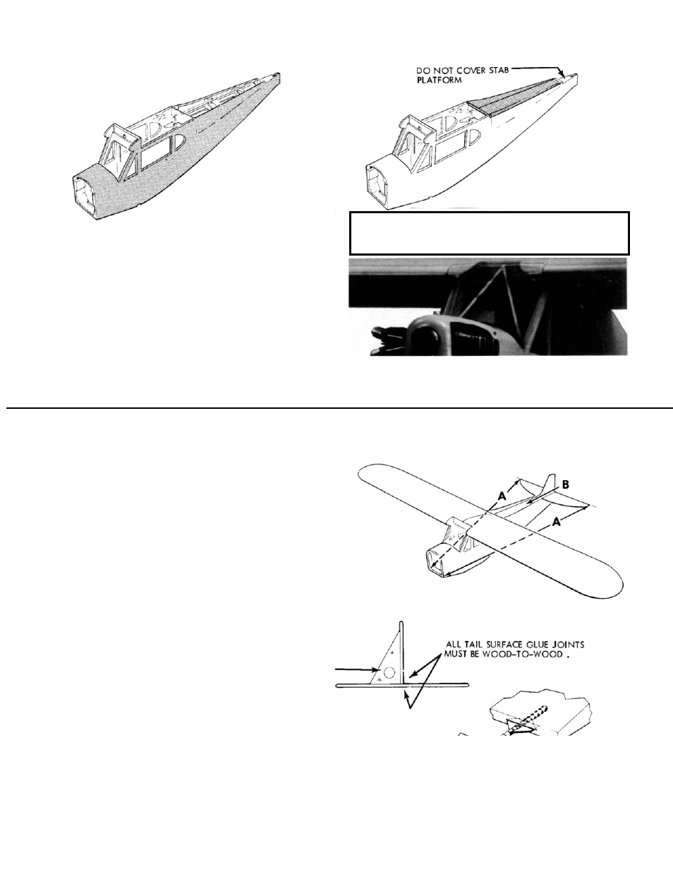
Cut and apply bottom covering to fuse.
Cut and apply side covering to fuse.
Carefully cut out window openings.
3.
Cut and apply top covering
(DO NOT COVER stab platform).
Important
THE WINDSHIELD IS NOT PERMANENTLY GLUED IN
PLACE UNTIL AFTER THE PUSH RODS ARE INSTALLED.
DECAL INSTRUCTIONS
For the instrument panel decal only, when cutting it from decal
sheet carefully trim it even with the black printed area to provide
a good fit on the dashboard. Apply panel and remaining decals
as described below.
Clean model surfaces thoroughly before applying decals
Cut decal sheets apart in sections as needed. Using
scissors, trim to within 1/8”. Carefully position decal on
model and stick in place. Working from center, rub decal
down while peeling off backing.
Cabin Front Trussing. For added scale detail, glue two
1/8” x 4-15/16” dowels in the cabin front as shown on the
label photo.
FINAL ASSEMBLY
When the wing is in place, a seal is needed to protect against the
entry of exhaust oil and dirt into the radio compartment. Also the seal
acts as a cushion between wing and fuse to prevent abrasion of the
covering. For this seal we recommend the use of silicone caulk. Since
it dries slowly, save this step as the last of a building session. Tape
plastic kitchen wrap around the wing center section. Apply a thin
ribbon of caulk to the wing rest surface on top of the fuse. Install
wing and bolt down moderately-do no wipe off the silicone that
squeezes out. Let dry overnight. Remove wing and using a sharp blade,
trim excess flush with fuse sides.
Bolt wing in place on fuse. Using no glue, trial fit stab in place on
fuse, adjusting as necessary to line up with wing. Then measure from
stab tips to fuse front (arrows ‘A’) to make sure stab is square with
fuse.
To provide a firm wood-to-wood glue joint, strip covering from
bottom of stab center where stab contacts fuse. Avoid cutting structure
underneath. Be certain to leave enough covering firmly bonded to stab
center (minimum 1/8” to 3/16”). Likewise, if stab area on fuse was cov-
ered, remove covering. Glue stab firmly to fuse and let dry.
Trial fit fin in place on stab (arrows ‘B’). Strip covering from fin
in bottom (if covered) and respective area on fuse/stab. Glue fin firmly
in place, and square with stab.
INSTALLING HINGES
IMPORTANT! Read and follow hinging instructions carefully. All
hinges must be firmly glued in place. Loose hinges can allow a control
surface to fall off, resulting in a crash! Tug hard on each hinge to
check bond.
When all the parts are ready for hinging then re-
mount the hinge with a pin inserted in the center. when satisfied
that all parts are aligned properly, remove pin. Apply 3 to 4 drops
of thin CA glue to the exposed hinge line. Turn over and apply
another 3 to 4 drops to the hinge line of the other surface.
Hinge elevator to stab. When dry, tug hard on each hinge to check
bond.
CONTINUED ON NEXT PAGE
Allow 10 minutes for the CA to cure, before flexing the sur-
face.
Work the surface up and down to remove any stiffness you
may feel.