B-plus – AERCO Adding a Communications Board to ECS User Manual
Page 3
3
MODBUS COMMUNICATIONS WIRING CONNECTIONS
Following installation of the Communications Board, wiring connections must be made
on the rear of the 2408 Controller to permit Modbus control by an Energy Management
System (EMS), Building Automation System (BAS), or Computer being used with the
Controller. To access the 2408 Controller wiring terminals and make the required wiring
connections, proceed as follows:
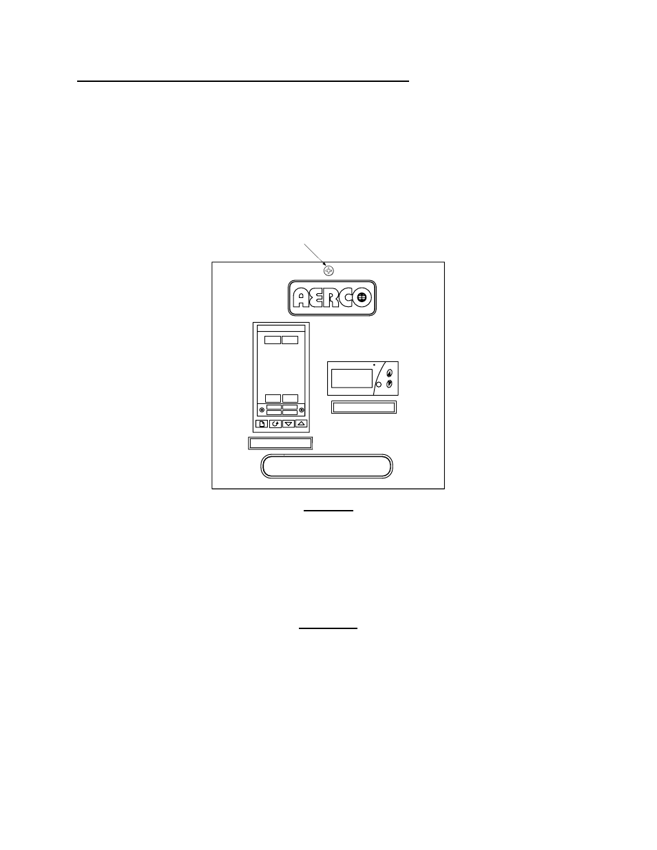
1. With the Control Box door open, loosen the captive screw at the top of the recessed
panel shown in Figure 4.
B-PLUS
TM
PT.NO.
SET
F
AUTO
RUN
MAN
HOLD
OP 1
OP 2
SP2
REM
2408
OVER TEMP SWITCH
TEMP CONTROLLER
PT.NO.
WATER HEATER
CAPTIVE SCREW
(LOOSEN TO OPEN)
Figure 4
2. Swing down the recessed panel to access the wiring terminal connections on the
rear of the 2408 Controller sleeve (Figure 5).
3. Refer to Table 1 and connect the appropriate wire leads to Temperature Controller
terminals listed.
CAUTION
DO NOT route Modbus communication wiring in the same
conduit as power wiring. Attempting to do so may result in
excessive noise on the signal lines. Also, ensure that the
RS232 or RS485 signal lead connections do not exceed the
following lengths:
• RS232 Wiring:
50 Feet Maximum
• RS485 Wiring:
4,000 Feet Maximum