Kistler-Morse KM Load Stand II User Manual
Page 12
97-1100-01 Rev. H
8
www.kistlermorse.com
• Check the wiring polarity at the K-M Test Meter. Ensure the red, white, and black wires are connected to the
corresponding terminals.
• If the wiring is correct and you still observe a negative output change, the vessel may be tilted. Vessel tilting
shifts the load onto some Load Stands while putting other Load Stand(s) in a no load or tension load condition.
This can occur in cases of extreme thermal deformation or unequal vessel leg length. Proceed to Step 2 to level
the vessel.
e. Repeat Steps A through D for each Load Stand for this vessel.
f. Calculate the average output change for all Load Stands for this vessel. The output increase for each
Load Stand must be within ±25% of the average output increase. Load Stands 1, 2, and 4 meet this
requirement, while Load Stand 3 does not.
g. If the installation meets the criteria described above (change in output is positive and is within ±25%
of the average output increase), the vessel is sufficiently level.
• If sufficiently level, proceed to Step 3 to complete the installation.
• If not sufficiently level, level the vessel as described in Step 2.
Load
Not Installed Installed Dead Weight
Output Change (mV)
Stand #
Output (mV)
Output (mV)
(Installed - Not Installed)
1
+30
+90
+60
2
-15
+50
+65
3
+17
+30
+13
4
-25
+30
+55
Average Output Change = (60 + 65 + 13 + 55) / 4 = 48.25
Allowable Range for Output Change = Average Output Change ± 25% = 48.25 ± (
1
/
2
x 48.25) = 36.18 to 60.3
All Load Stands meet the requirement that all output changes must be positive (+).
Load Stands 1, 2, and 4 meet the
requirement that the output change be within ± 25% of the average output change. Load Stand 3 does not meet the
requirement, and its small output change indicates it is carrying much less weight than the other supports. The vessel
must be leveled to distribute the weight more evenly over all the supports.
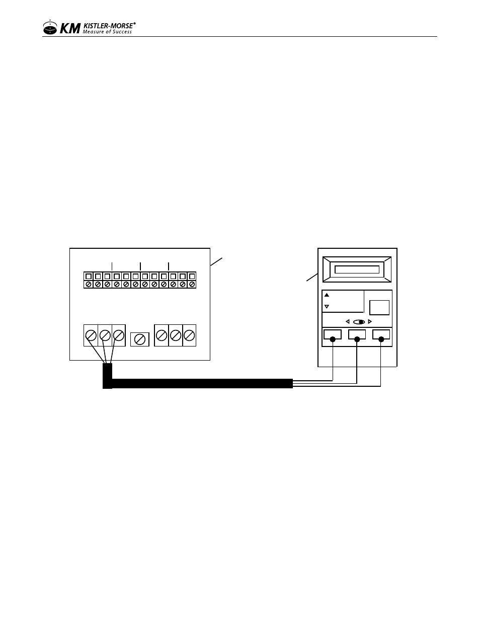
Checking Output using Kistler-Morse Test Meter
B W R SHLD B W R
TB1 TB2
B W R B W R B W R B W R
SENSOR A SENSOR B SENSOR C SENSOR D
LOAD STAND STANDARDIZATION
TB3
Red White Black
ON
OFF
SENSOR
TEST
METER
ADJUST
SIMULATE
TEST
+EX
SIGNAL
-EX
Junction Box PCB
Note: Wiring from sensors to
terminal TB3 not shown for
clarity.
KM Test Meter
Example — Recording and Analysis of Output for Level Check