Kistler-Morse KM Load Stand II User Manual
Page 11
7
www.kistlermorse.com
97-1100-01 Rev. H
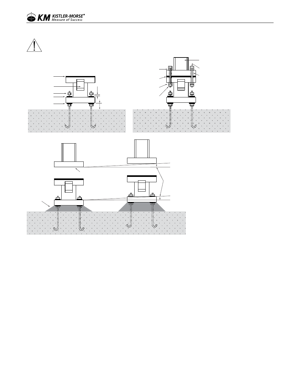
caution: iF inStaLLinG ShiMS, LooSen the toP BoLtS on aLL the LoaD StanDS BeFore
raiSinG the veSSeL.
Rubber Washer
From Kistler-Morse
Vessel Leg and
Mounting Plate
Bolt
Center Load Stand
top mounting holes
with vessel mounting
holes. Center bolts in
mounting holes.
(Bolts and holes shown
for clarity.)
Rubber Pad
From Kistler-Morse
Rubber Washer
From Kistler-Morse
Nut
Rubber Pad
From Kistler-Morse
Junction Box
Leave 1/4 in.
(6 mm) Gap
Minimum 2 in.
(51 mm) for Grout
Nut
Washer
Leveling Nut
and Washer
Grout:
Not installed
until after vessel
is leveled.
Vesssel Mounting Surface
No more than
minimum of ±1º
or 1/4 in. (6 mm)
LeveLinG the veSSeL
Leveling the vessel distributes the weight evenly on all the Load Stands, increasing system accuracy. Perform
this procedure while the vessel is still empty:
1. Check if Leveling Needed
a. Remove the junction box cover.
b. Connect the red, white, and black wires of a 3-conductor cable to the corresponding terminals on TB1 of
the Load Stand junction box. Connect the other end of the cable to the corresponding terminals of the K-M
Test Meter. Turn on the power to the Test Meter and set the Simulate/Test switch to the Test position.
note: If a Kistler-Morse Test Meter is not available, before proceeding refer to Set-Up; Alternate Method for
Checking Output.
c. Verify the dead weight voltage output of the Load Stand from step 3f.
d. Calculate the change in output, as shown in the example. Output Change = uninstalled output
- installed output. The change in output must be positive.