Iv. mechanical installation – Kistler-Morse KM InvisiLink User Manual
Page 8
www.kistlermorse.com
4
97-1502-13 Rev. C
IV. MECHANICAL INSTALLATION
WARNING: REMOVE POWER FROM THE UNIT BEFORE INSTALLING REMOVING OR MAKING
ADJUSTMENTS.
CAUTION: DO NOT ROUTE SERIAL CABLES IN THE SAME CONDUIT WITH AC POWER CABLES.
CAUTION: THIS DEVICE COMPLIES WITH PART 15 OF THE FCC RULES. OPERATION IS
SUBJECT TO THE FOLLOWING TWO CONDITIONS: (I) THIS DEVICE MAY NOT CAUSE HARMFUL
INTERFERENCE AND (II) THIS DEVICE MUST ACCEPT ANY INTERFERENCE RECEIVED, INCLUDING
INTERFERENCE THAT MAY CAUSE UNDESIRED OPERATION.
MOUNTING CONSIDERATIONS
• Mounting hardware is not supplied by Kistler-Morse.
• When mounting the enclosure ensure there is enough clearance to open the front door
completely. Removal, insertion, and wiring of the modular PCB is done through the front of
the unit.
• Preferred direct line of sight between antennas (devices)
• Minimize metallic obstacles between devices
• Should not be close to high voltage sources
WHEN SEALING CONDUIT CONNECTIONS, ONLY USE SIKAFLEX 1A POLYURETHANE SEALANT
OR DOW CORNING RTV 738 OR 739. OTHER SEALANTS MAY CONTAIN ACETIC ACID WHICH IS
HARMFUL TO SENSORS AND ELECTRONICS.
DRILLING HOLES IN THE ENCLOSURE
The standard fiberglass NEMA 4X rated enclosure has no openings through which to route cables or
install the conduit. Hole location is critical for proper conduit installation. Check clearances to ensure
that the fittings and wire routing will not interfere with the PCB or enclosure door.
DO NOT DRILL HOLES THROUGH THE TOP OF ENCLOSURE AS THIS MAY ALLOW MOISTURE
SEEPAGE, WHICH CAN DAMAGE THE ELECTRONICS AND VOID THE WARRANTY.
PREPARE THE ENCLOSURE FOR CONDUIT
1. Open door of the enclosure.
2. Remove all four (4) mounting screws that attach the board to the
enclosure.
3. Remove entire board, and place in a safe location.
4. Make a separate hole for the AC cable, the serial and CAT 5 wiring.
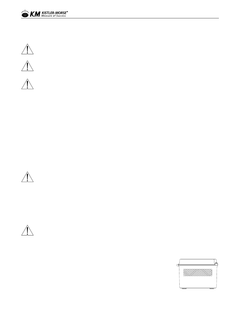
Figure 1. Bottom View