Vi. set-up, Led layout and indications db-9 – Kistler-Morse KM InvisiLink User Manual
Page 13
www.kistlermorse.com
9
97-1502-13 Rev. C
VI. SET-UP
1. The enclosure has been mounted.
2. Determine Point to Point or Multi-Point configuration. See Figure 10 for Dip Switch settings.
3. Serial cable has been wired, and power has been wired and turned on.
4. Ensure the Power Indicator LED light is solid red and that Serial Data In/Out LEDs are flashing.
See Figure 5.
No additional programming is required. All radio enclosures should automatically begin sending and
receiving signals.
NOTE: Communication device types cannot be mixed. RS-485 devices must be connected to another
RS-485 device; it will not receive signals to or from a RS-422 device.
To ensure unit is functioning properly, check the LED indicator lights.
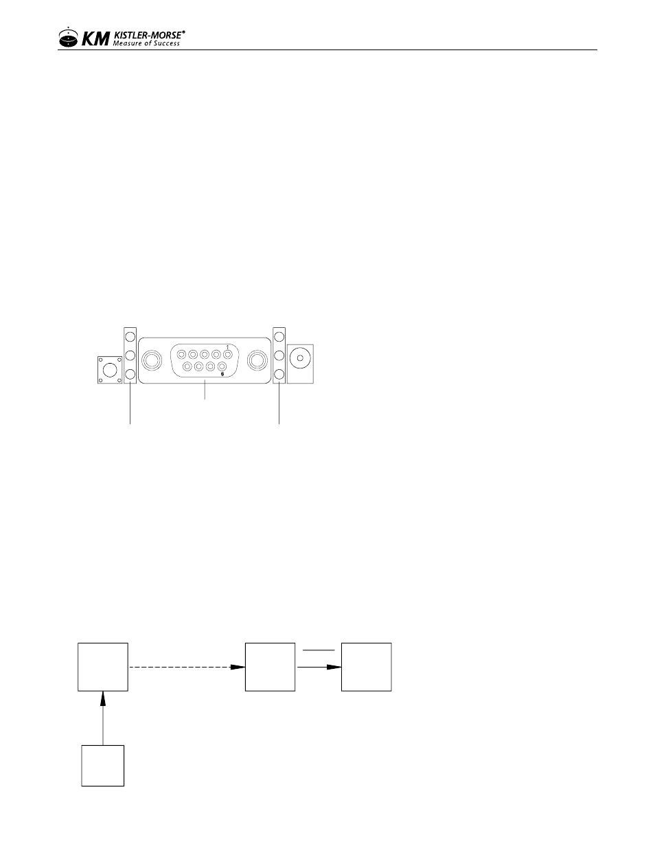
Figure 5: LED Indicator Lights
Indicator LEDs
Yellow (top) = Serial Data Out (to host)
Green (middle) = Serial Data In (from host)
Red (bottom) = Power/TX Indicator (Red light
is on when powered; it pulses on/off briefly
during RF transmissions
DB-9 Serial Port
RSSI LEDs - Strength of signal
3 LEDs ON = Very Strong Signal
2 LEDs ON = Strong Signal
1 LED ON = Moderate Signal
0 LED ON = Weak Signal
LED Layout and Indications DB-9
If indicator lights are not working, please proceed to the Troubleshooting section of this manual for
assistance.
Notes (Use for Figures 6-9):
1. All remote devices must use the same protocol.
2. If device protocol = RS485, then InvisiLink Base must be RS485.
If Device Protocol = RS422 or 4-20 mA, then InvisiLink Base must be RS422.
Figure 6. Point-to-Point
InvisiLink
Remote
InvisiLink
Base
ORB
or
PLC
Device
RS485
RS422
RS485
RS422
Note 1
Note 2