Kistler-Morse KM InvisiLink User Manual
Page 15
www.kistlermorse.com
11
97-1502-13 Rev. C
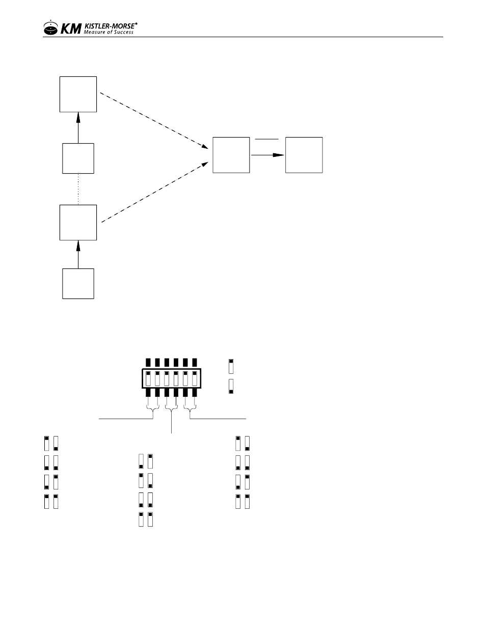
Figure 9. Multi Point
InvisiLink
Remote
Device
RS485
RS422
Note 1.
InvisiLink
Remote
Multi-Point Remote
Multi-Point Remote
(N)
Device
RS485
RS422
Note 1.
InvisiLink
ORB
or
PLC
RS485
RS422
Note 2.
(N) = Max of 50 Devices.
Each remote must be identical and
match the base protocol.
Multi-Point Base
To set multi-point units, see figure 10 for dip switch settings.
Figure 10: Dip Switches
Serial Interface
Switches 1 & 2
RS-485/422 Termination
Switches 3 & 4
TX/RX Mode
Switches 5 & 6
1 2 3 4 5 6
= 2-wire RS-485
= Not used
= Factory Reserved
= 4-wire RS-422
= Multipoint-Base
= Point-to-Point
= Factory Reserved
= Multipoint-Remote
= 2-wire RS-485
Termination
= Factory Reserved
= Factory Reserved
1 2
3 4
5 6
= None
= ON (up)
= OFF (down)
NOTE: Point to point is used when one radio is talking to one radio only; multi-point is used when
there are multiple remotes and/or bases.