Kistler-Morse KM InvisiLink User Manual
Page 12
www.kistlermorse.com
8
97-1502-13 Rev. C
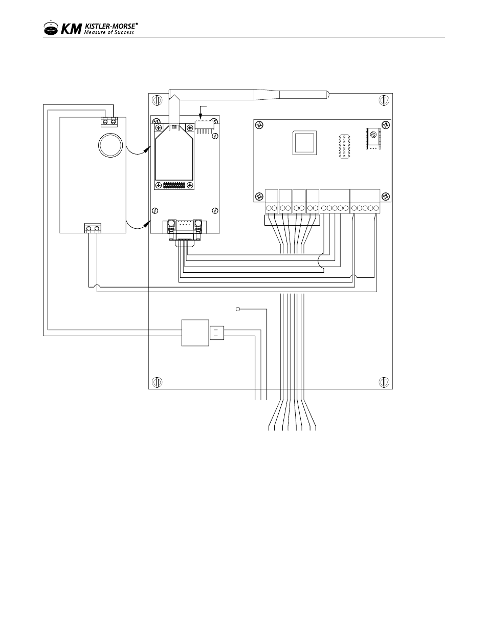
Figure 4: Wiring Diagram RS-422 with 4-20 mA Input Box
2 POS
CONN.
WIRING DIAGRAM RS-422 W/4-20
5
1
4 3 2
9 8 7 6
Pin 5 - Orange
Pin 9 - Blue
N
L
PW
R
CUSTOMER
WIRING
GN
D
N
L
GND
This Power Board
is mounted under the
Wireless Board to the right.
The (2) boards are shown
side-by-side for clarity.
-
+
IN
+
IN
-
OU
T+
OU
T-
Pin 2 - Gray
Pin 3 - Yellow
Pin 7 - Brown
Pin 8 - Green
+
-
+
-
+
-
+
-
Ch.1
Ch.2
Ch.3
Ch.4
+
-
+
-
+
-
+
-
Ch.1
Ch.2
Ch.3
Ch.4
4-20mA
N
L
-
+
Figure 6.