3 select the frequency band, 4 connect input/output cabling, 5 mount the receiver – Inovonics EN4216MR User Manual
Page 2: 6 factory configuration defaults, 7 system status, 8 point status, 9 install & service
© Inovonics, 2011 - www.inovonics.com
2
3 Select the Frequency Band
EchoStream products use a range of radio frequencies, and must be
configured for your geographic area. To configure the receiver:
1. Use a small screwdriver to press the housing release tabs on the top or
bottom of the receiver; separate the housing.
2. Place a selection jumper on the appropriate frequency band selection
pins.
• Leave the jumper off the pins to set the frequency range to 902-928
MHz for North America.
• Place the jumper on the top two pins, marked NZ, to set the frequency
range to 921-928 MHz for New Zealand
• Place the jumper on the bottom two pins, marked AUS, to set the
frequency range to 915-928 MHz for Australia.
Note: North American is also selected when the jumper is only attached to
one pin. This can prevent the jumper from being lost when selecting North
America.
Note: Only devices set for use in North America are configured for UL
installations.
3. Cycle power to reset.
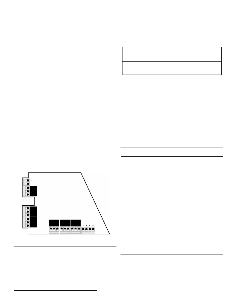
4 Connect Input/Output Cabling
1. Connect cabling to the receiver power loss output. Must be configured
for UL installations.
• The receiver power loss output is a normally closed (N/C) output that
opens when the receiver loses power.
2. Connect cabling to the tamper output. Must be configured for UL
installations.
• The tamper output is a normally open (N/O) output that reports
receiver case tamper to an external device.
3. Connect cabling to the jam output. Must be configured for UL
installations.
• The jam output is a normally closed (N/C) output that opens when
noise thresholds on all receive channels remain above a
predetermined value for 10 seconds. The jam output is set to the
follower output type.
4. Connect a momentary switch to the reset input and ground. Must be
configured for UL installations.
• The reset input circuit permits installation of a remote momentary
normally open (N/O) switch to clear faults, unlatch outputs, and reset
the receiver to a normal state.
5. Connect cabling to the output terminals. Must be configured for UL
installations.
• The EN4216MR provides six Form-C relays.
6. Close receiver housing.
Figure 4 EN4216MR Terminals
5 Mount the Receiver
Caution: Mount the receiver in a location removed from metal. Metal
objects (duct work, wire mesh screens, boxes) will reduce RF range.
Note: For UL listed systems containing a UL hold-up switch, the
EN4216MR must be located within three feet of a system keypad in a
location out of sight from the protected premise.
Note: For UL installations, the EN4216MR must be in the same room as
the control panel.
1. Use the provided anchors and screws to mount the receiver in a
location accessible for future maintenance.
2. Perform a walk test, activating each transmitter assigned to the receiver
and ensuring a good signal.
6 Factory Configuration Defaults
The EN4216MR arrives with the tamper, low battery, and inactive trouble conditions
pre-programmed.
Default Trouble Condition Programming
7 System Status
System status information displays alarm and fault information on the LCD
display by default. Points in alarm are displayed as A
LARM
, with the point
number following. If more than one point is in alarm, the display scrolls
through each point. If a point has more than one alarm, the display scrolls
through each alarm. Fault conditions are indicated by F
AULT
in the LCD
display if there is no A
LARM
already displayed; point numbers are not
displayed. If no point is in alarm and there are no fault conditions, R
EADY
displays.
8 Point Status
P
OINT
S
TATUS
allows you to view detailed alarm and fault information. Point
status information is available without a password.
To access P
OINT
S
TATUS
:
1. From system status information, press the Enter button to access the
receiver’s three main menus. P
OINT
S
TATUS
displays.
2. Press Enter to display point status details.
3. Use the Up/Down buttons to scroll through the points; press Enter
again to view the outputs the displayed conditions are mapped to.
• Point status flags are defined as follows: A = Alarm (transmitter only);
T = Tamper; B = Low Battery; L = AC loss (repeater only); I = Inactive.
Note: If - - displays, the displayed condition has been mapped to a null
output.
9 Install & Service
Note: The default password is 3446.
The I
NSTALL
& S
ERVICE
menu is used to reset factory configuration, change
password, view signal strength, delete points, register transmitters, and
setup points for any of the programmed points.
To access the I
NSTALL
& S
ERVICE
menu:
1. From the system status information, press the Enter button to access
the receiver’s three main menu options.
2. Use the Up and Down buttons to navigate to the the I
NSTALL
& S
ERVICE
menu; press the Enter button.
3. Enter a password to access I
NSTALL
& S
ERVICE
menus.
9.1 Setup Point
1. From the I
NSTALL
& S
ERVICE
menu, press Enter at the S
ETUP
P
OINT
prompt.
2. Use the Up/Down buttons to scroll through point numbers; press the
Enter button to select a point.
• T
X
R
EGISTR
’
D
displays if a transmitter or repeater is currently
registered to this point; T
X
N
OT
R
EGSTR
’
D
displays if no transmitter is
registered to this point.
3. Press Enter to continue.
Supervision Time: Sets a time limit on missing transmitters.
• The valid range is 0 to 99 hours. The default is 60 minutes. Selecting
0 turns off supervision.
Caution: Turning off supervision can jeopardize the integrity of your
system. Inovonics does not recommend turning off supervision. For
supervision to function correctly, the supervision time must be set for an
interval greater than the transmitter check-in time.
a. Use the Up and Down buttons to adjust the supervision time; press
the Enter button to select.
b. Use the Up and Down buttons to toggle between Hrs (hours) and Min
(minutes); press the Enter button to select.
Select Security/Repeater: Configures point’s alarm and alert messages
as either a repeater or a security transmitter.
a. Use the Up and Down buttons to choose S
ELECT
S
ECURITY
for a
security transmitter or S
ELECT
R
EPEATER
for a repeater; press the Enter
button to select.
Vs
Jam
ou
tpu
t
Ground
T
a
mp
er out
pu
t
Reset
inp
u
t
Recei
ver
po
w
e
r loss
ou
tp
ut
Caution:
Incorrect
connections
may cause
damage to the
unit
NC
COM
NO
NC
COM
NO
NC
COM
NO
NC
COM
NO
NC
COM
NO
NC
COM
NO
Condition
Output
Tamper
6
Low Battery
5
Supervision Loss/Inactive
6