5 | electrical connection – GEA Bock HG88e User Manual
Page 25
D
GB
F
E
I
Ru
25
96260-11.2014-DGbFEIRu
5| Electrical connection
5.8 Function test of the trigger unit INT69 G
Before commissioning, after troubleshooting or making changes to the control power circuit, check
the functionality of the trigger unit. Perform this check using a continuity tester or gauge.
Gauge state
Relay position
Deactivated state
11-12
INT69 G switch-on
11-14
Remove PTC connector
11-12
Insert PTC connector
11-12
Reset after mains on
11-14
Relay position INT69 G
B2 12 14 11
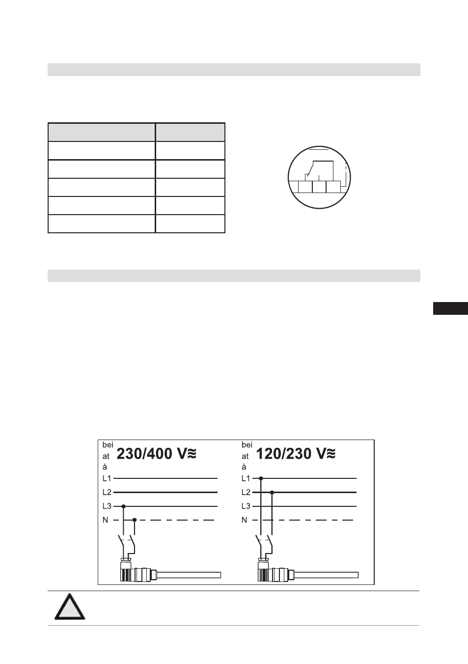
5.9 Oil sump heater (accessories)
Anschlussschema für Ölsumpfheizung
Connection diagramm for oil sump heater
Plan de raccordement pour résistance de carter d‘huile
09983- 10.01-DGBF
D
GB
F
When the compressor is at a standstill, refrigerant diffuses into the lubricating oil of the compressors
housing, depending on pressure and ambient temperature. This reduces the lubricating capacity of
the oil. When the compressor starts up, the refrigerant contained in the oil evaporates out throught the
reduction in pressure. The consequences can be foaming and migration of the oil, causing oil shocks
under certain circumstances.
Operation: The oil sump heater operates when the compressor is at a standstill. When the compres-
sor starts up, the oil sump heater switches off again automatically.
Connection: The oil sump heater must be connected via an auxiliary contact (or parallel wired auxili-
ary contact) of the compressor contactor to a seperate electric circuit.
El. data: 230 V - 1 - 50/60 Hz, 200 W.
Fig. 25
Fig. 24
ATTENTION
Connection to the current path of the safety control chain is not
permitted.