A-125, System a - 100, Doepfer – Doepfer A-125 VC Phaser User Manual
Page 6
A-125
VC Phaser
System A - 100
doepfer
6
The phaser is simply inserted in the audio path like
this. For modulation sources, you could use, for
instance, any of the following:
P
With the last two of these alternative modula-
tors particularly, you can optionally use an
A-170 Slew Limiter after them, to smooth out
sudden jumps of control voltage, and make
the phasing transitions less abrupt.
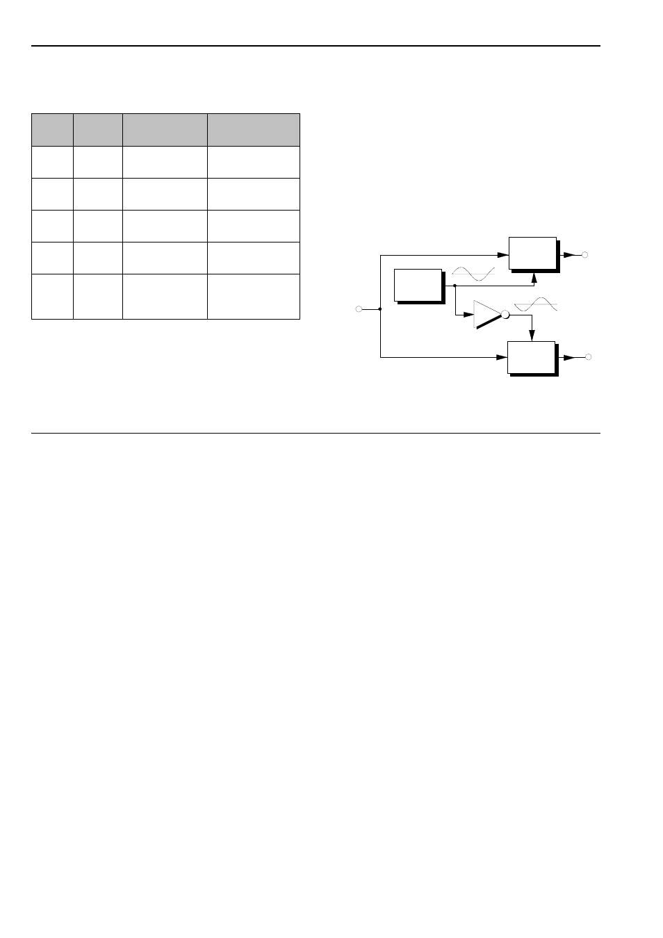
"Stereo"-Phasing
Using two A-125s and the patch in Fig. 4 you can
create a wide pseudo-stereo phasing effect, with inver-
ted signals coming out of each of the two audio
channels (Out
L
und Out
R
).
Typically, you can use a slow LFO to provide the
modulation for the phase shift, but any other modulator
will work, as with standard phasing. Phaser VCP 1 is
fed the modulation from the LFO directly, while an
A-175 voltage inverter is patched in before the second
phaser VCP 2, to invert the modulation.
Fig. 4: "Stereo" phasing
Alter-
native
Module
Adjustment
Effect
1
LFO
A-145
low frequency
(< 2 Hz)
free-running
phase-shift
2
ADSR
A-140
slow envelope
keyboard-
controlled phaser
3
Random
A-118
slow random
rate
random phasing
4
S&H
A-148
random phasing
5
A-190
CV 2
any MIDI con-
troller for CV 2
(eg. velocity)
MIDI - controlled
phasing
LFO
A-175
Audio
In
Out
L
Out
R
VCP 1
CV
VCP 2
CV