System a - 100, A-125, Basic principles – Doepfer A-125 VC Phaser User Manual
Page 3: Doepfer, Vc phaser
doepfer
System A - 100
VC Phaser
A-125
3
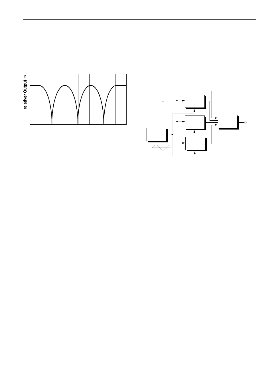
3. Basic principles
The phasing process relies on dynamic comb filtering.
The comb filtering produces a series of gaps in the
audio spectrum (in Fig. 1, at 200 Hz, 1 kHz and 5
kHz), by the cancelling process which is created byha-
ving identical sounds 180° out of phase with each
other (or ‘inverted’).
Fig. 1: The principle of phasing
These zero points are continuously swept through the
audio spectrum, cancelling out different frequencies,
and producing the characteristic phasing sound.
The principle can be explained by looking at the dia-
gram (Fig. 2) of a phaser created by three band pass
filters. Here, audio is input to the three filters BP1 to
BP3 (notch filters also work), set to different middle
frequencies. A slow LFO modulates the frequencies.
The outputs of the band pass filters are then mixed
with the original signal. Because of the phase reversal
inherent in the filter design (most apparent close to the
middle frequency), different areas of the audio
spectrum are cancelled out.
Fig. 2: A phaser model using separate modules
50
100
200
500
1k
2k
5k
10k
20k
Frequenz [Hz] Ц
Ц
Ц
Ц
BP 1
LFO
Mixer
Audio In
Out
f ~ 3 Hz
f = x Hz
c
BP 2
f = y Hz
c
BP 3
f = z Hz
c