Doepfer – Doepfer A-122 24dB Low Pass 2 User Manual
Page 6
A-105 / A-122
System A - 100
doepfer
6
A-121 multi-mode filter’s 12 dB) with voltage control-
led resonance.
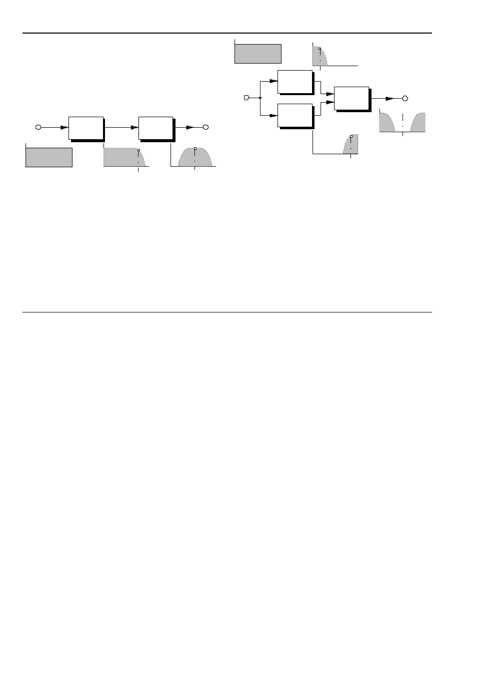
To create a bandpass filter, put both modules in
series (see Fig. 3). The band-width is governed by the
difference between the cut-off frequencies of the two
filters f
L
(A-122) and f
H
(A-123); the middle frequency
is half way between the two: f
M
= (f
L
+ f
H
) / 2.
Fig. 3: 24 dB band pass filter (resonance = 0)
A notch filter is created by putting both modules in
parallel, and controlling their outputs with an A-138
mixer (see Fig. 4). The band-width and middle fre-
quency are determined by the same factors as in the
bandpass.
When modulating these ‘construction kit’ filter types,
certain rules apply:-
Fig. 4: 24 dB notch filter (resonance = 0)
• To maintain the exact bandwidth, the cut-off
frequencies of both filters must be modulated by
the same amount.
• If you modulate the cut-off frequency of just one of
the filters, or both of them by different amounts, or
different modulators, the bandwidth and middle
frequency will themselves be modulated.
• At a resonance setting of greater than zero, or
when the resonance is modulated, the middle fre-
quency will be skewed. With different resonance
settings or modulation of each filter, this will have
the same result.
A-122
Freq. Ö
f L
f
M
Freq. Ö
Freq. Ö
A -123
f H
Fre q.
Ö
A-122
Freq. Ö
A-123
Freq. Ö
A-138
Freq. Ö
f
M
f
L