Doepfer Dial Electronic User Manual
Page 8
DIAL ELECTRONIC
Page 8
User's Guide
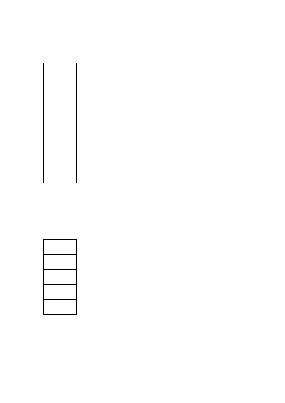
Connector for 6 control switches (5)
The pin header JP1 is used to connect 6 control switches (momentary switches,
buttons). This is the pin out of JP1 (refer to the picture on page 6):
Each of the 6 switches (labelled T1 ... T6) has two terminals (a
and b) that have to be connected to the corresponding pins of
the pin header. The first switch has to be connected to the pins
T1a and T1b, the second to T2a and T2b and so on. Simple
momentary switches (open at rest) are used.
The 4 lower pins are not used (NC = not connected).
We recommed the usage of a 16 pin female connector with 16
pin ribbon for this connection. The switches are soldered to the
open ends of the ribbon cable. The female connector with
ribbon cable is included with the DE control set.
Connector for 4 LEDs (6)
The pin header JP2 is used to connect 4 LEDs. This is the pin out of JP2 (refer to the
picture on page 6):
Each LED has two terminals: + (positive terminal or anode) and
– (negative terminal of cathode). The shortened LED pin is
normally the cathode. Each of the 4 LEDs is connected to the
corresponding pins Lx+ (positive LED terminal) and Lx-
(negative LED terminal). The first LED is connected to L1+ and
L1-, the second to L2+ and L2- and so on. Almost each LED
type can be used (3mm / 5mm / rectangle, red / orange / yellow
/ green / blue / white).
The two upper pins of JP2 are not used (NC = not connected).
We recommed the usage of a 10 pin female connector with 10
pin ribbon for this connection. The LEDs are soldered to the
open ends of the ribbon cable. The female connector with
ribbon cable is included with the DE control set.
T1a
T1b
T2a
T2b
T3a
T3b
T4a
T4b
T5a
T5b
T6a
T6b
NC
NC
NC
NC
NC
NC
L1+
L1-
L2+
L2-
L3+
L3-
L4+
L4-