Domestic compact electrical systems – Cub Cadet 5000 Series User Manual
Page 89
Domestic Compact Electrical Systems
85
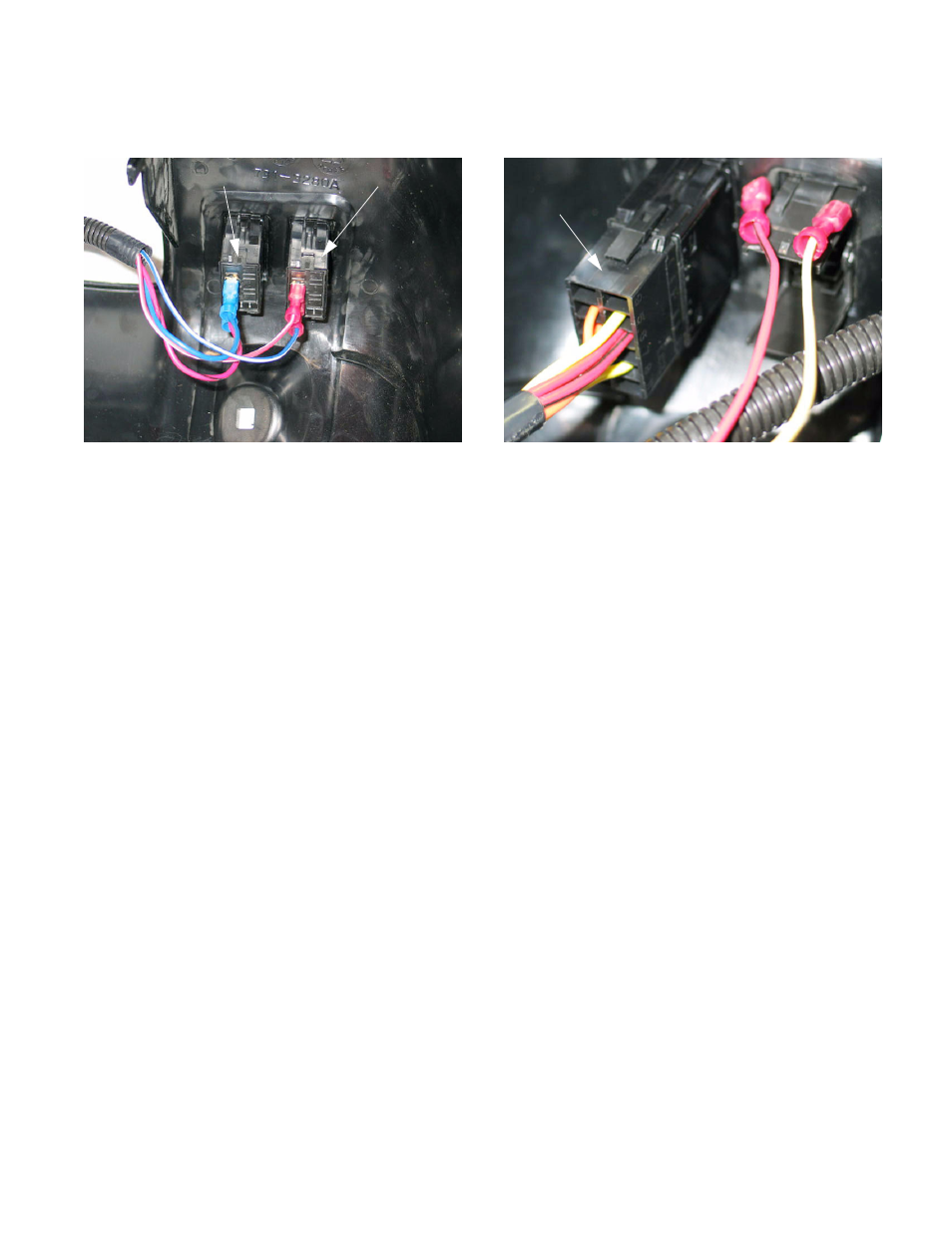
2.9.
The hazard flasher draws constant hot through
the red wire with white trace. See Figure 2.9.
•
When the contacts are closed (hazard switch
ON), power is passed to the hazard lights via
flasher relay through the blue wire with white
trace.
•
The hazard circuit extends beyond the lights,
back to the instrument panel, illuminating
arrows: pin #10 = left arrow Pin #21 = right
arrow.
•
The headlight switch gets power from the red
wire with black trace when the key switch is ON.
•
When the contacts are closed (headlight switch
ON), power is passed to the headlights through
the blue wire.
•
The headlight circuit extends beyond the lights,
to the instrument panel (pin # 3) where it illumi-
nates a headlight indicator.
•
Not all Series 5000 tractors are equipped with
hazard flashers.
•
The female spade connectors are color coded:
Red for the Hazard circuit
and
Blue for the Head-
light circuit.
Figure 2.9
Headlight
switch
Hazard flasher
switch
2.10. The PTO switch is more complex.
•
The PTO switch contains two sets of contacts:
one in the starter circuit, and the other in the
engine shut-down and PTO circuits.
•
The orange wire (starter circuit) brings power
form the key switch in the START position.
•
If the PTO switch is turned OFF, the contacts
close, passing power to the orange and black
wire.
•
The orange and black wire conducts power to
the brake switch.
•
The red wires with black traces conduct power to
the second set of contacts within the PTO switch
when the key switch is ON.
•
If the PTO switch is ON, contact is made to the
yellow wire with white trace, providing power to
the common terminal on the PTO relay
•
If the PTO switch is OFF, contact is made to the
plain yellow wire, leading to the brake switch.
Figure 2.10
PTO switch