Domestic compact electrical systems – Cub Cadet 5000 Series User Manual
Page 88
Domestic Compact Electrical Systems
84
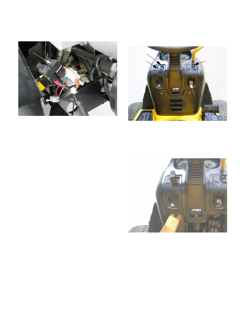
2.6.
Kohler powered tractors use a similar engine kill
relay arrangement. See Figure 2.6.
•
Engine kill relay has red, green, and black wires.
•
When the red wires are hot, the relay is ener-
gized, pulling the normally closed contact open,
breaking the path that grounds-out the magneto.
•
When power is taken away from the red wire by
turning the key switch to OFF, the relay de-ener-
gizes, and the magneto is grounded when the
normally closed contact (magneto primary wind-
ings) connects with the common contact
(ground)
•
A second relay controls the charge circuit and
after-fire solenoid (red wires, and red wires with
white trace).
•
When the key is ON, regulator out-put and the
after-fire solenoid are connected to the battery:
charging the battery and powering the solenoid.
•
When the key is OFF, the relay is de-energized,
breaking contact with the battery. With the after-
fire solenoid receiving power only from the regu-
lator, the fuel flow stops when the rotor (fly-
wheel) stops turning.
2.7.
Located on the dash panel are the hazard
flasher switch, light switch, PTO switch, Key
switch, and instrument panel. See Figure 2.7.
2.8.
With the access panel removed, any of the
rocker switches can be taken out of the dash
panel by squeezing the retaining tabs.
See Figure 2.8.
Figure 2.6
Main fuse
Charge
Kill relay
relay
Kohler-powered
tractor
Figure 2.7
Lights
Hazard
PTO
Key switch
Figure 2.8