Domestic compact dash and steering pump – Cub Cadet 5000 Series User Manual
Page 80
Domestic Compact Dash and Steering Pump
64
2.4.
The throttle cable can be removed from the
throttle assembly by squeezing the barbs on the
cable end.
2.5.
The lock nut, flat washer and two bellville wash-
ers can be removed from the base of the throttle
lever, using a 9/16” wrench. See Figure 2.5.
2.6.
The throttle lever can then be removed from the
throttle assembly. See Figure 2.6.
2.7.
The throttle assmebly can be unbolted fromt he
dash panel using a 7/16” wrench.
See Figure 2.7.
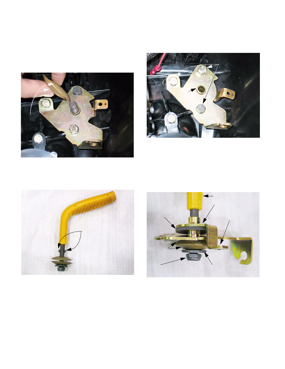
2.8.
The correct order of assembly for the throttle is:
throttle tab, friction washer, mounting plate, two
bellville washers (face-to-face), flat washer ,
locking nut. The throttle lever passes through all
of these parts, with the ears on the lever engag-
ing the slots in the throttle tab. See Figure 2.8.
NOTE: The throttle lever should be extend in the
same direction as the arm on the throttle tab.
The ears on the throttle lever allow it to be
installed in one of two positions: aligned with the
arm, or 180 out, facing the opposite direction.
Figure 2.5
Throttle assembly:
nut, flat washer & cable
removed
Two belleville
washers:
face-to-face
Figure 2.6
Ears
Figure 2.7
Notch
Mounting bolts
Figure 2.8
Throttle lever
Throttle tab
Friction
washer
Nut
Flat washer
Belleville
washers
Arm on
throttle tab