Cub Cadet C-155G User Manual
Page 9
NOTE: If the openings on each end of
the steering bellow are two different
sizes, the smaller end goes down
against the dash of the lawn tractor.
•
Position the front wheels of the tractor so
they are pointing straight forward.
•
Place the steering wheel over the steering
shaft, positioning steering wheel as de-
sired.
•
Place the washer
with the cupped
side down over
the steering shaft.
Secure with hex
bolt. See Figure 2.
•
Place the steering wheel cap over the
center of the steering wheel and seat it
with your hand. See Figure 2.
•
If your unit is equipped with a steering in-
sert packed in a plastic bag with the
literature, snap it over the round steering
wheel cap. See Figure 2.
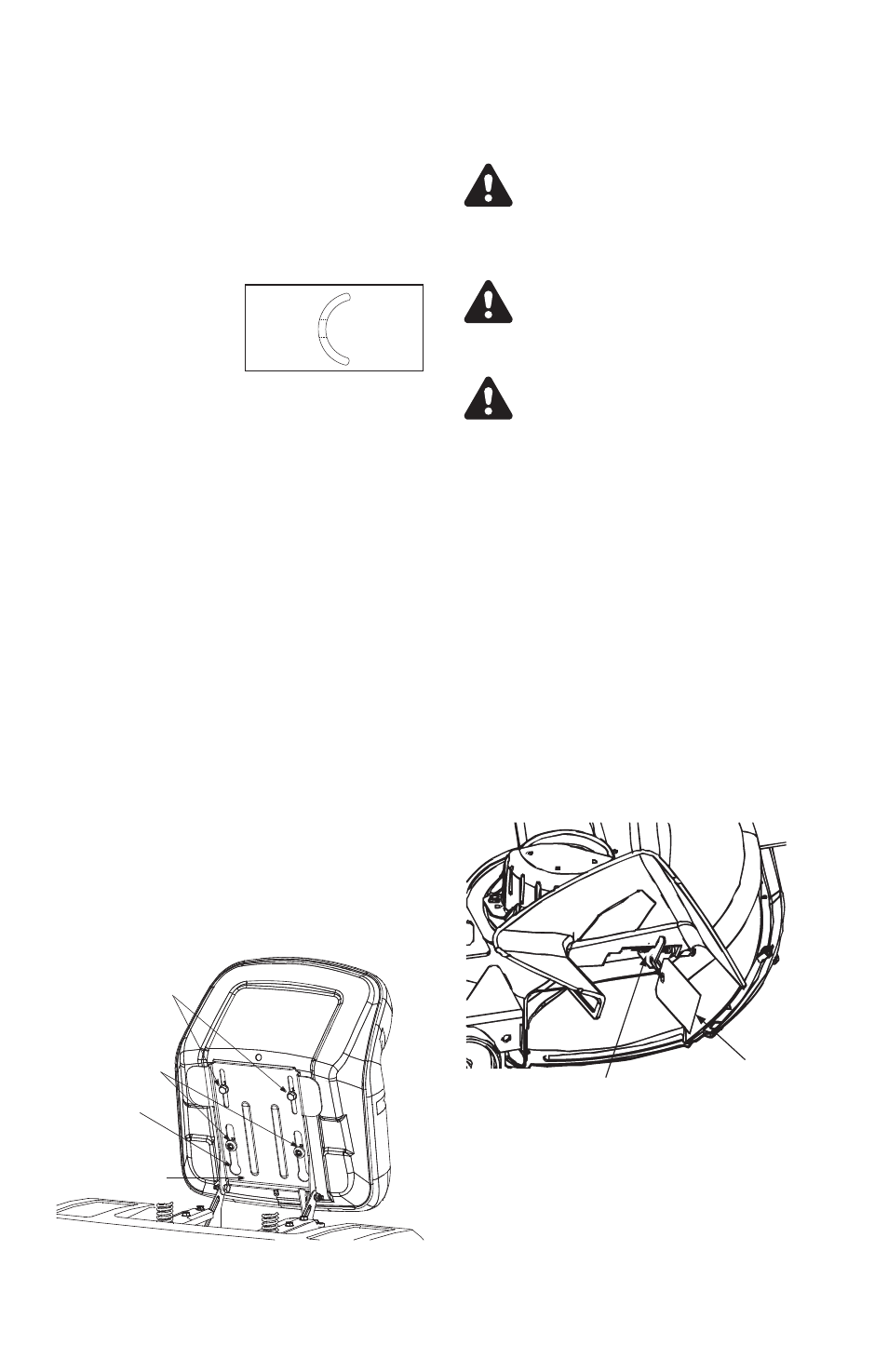
ATTACHING THE SEAT
For shipping reasons, seats are either fas-
tened to the tractor seat’s pivot bracket with
a plastic tie, or mounted backward to the
pivot bracket. In either case, free the seat
form its shipping position and remove the
two hex screws (or knobs, on models so
equipped) from the bottom of seat before
proceeding with instructions below.
•
Position the shoulder screws (found on the
base of the seat) inside the slot openings
in the seat pivot bracket.
•
Slide the seat slightly rearward in the seat
pivot bracket, lining up the rear slots in the
pivot bracket with the remaining two holes
in the seat’s base.
•
Select desired position for the seat, and
secure with the two hex screws/knobs re-
moved. Do not overtighten. See Figure 3.
Shipping Brace Removal
WARNING: Make sure the tractor’s
engine is off, remove the key from
the ignition switch and apply the
tractor’s
parking
brake
before
removing the shipping brace.
WARNING: The shipping brace,
used for packaging purposes only,
must be removed and discarded
before operating your riding mower.
WARNING: The mowing deck is
capable of throwing objects. Failure
to operate the tractor without the
discharge chute properly in place
could result in serious personal
injury and/or property damage.
•
Locate the shipping brace and accompa-
nying warning tag on the right side of the
mower, between the discharge chute and
the cutting deck. See Figure 4.
•
While holding the discharge chute with
your left hand, remove the shipping brace
with your right hand by grasping it be-
tween your thumb and index finger and
rotating it clockwise.
•
Carefully allow the discharge chute to pivot
downward. See Figure 4.
•
Discard the shipping brace and accompa-
nying warning tag.
INSTALLING THE MULCHING PLUG
(optional)
•
Locate the square hole found in the cutting
deck surface by pivoting the discharge
chute upward.
9
FIGURE 3
Hex Screws
(optional knobs)
Shoulder
Opening in
Slot
Pivot
Bracket
FIGURE 4
Warning Tag
Shipping Brace
Cupped
Side
Crowned
Side