Cub Cadet C-155G User Manual
Page 15
NOTE: Check the tractor’s tire pres-
sure before performing any deck
leveling adjustments. Refer to Tires
later in this section for further informa-
tion regarding tire pressure.
The front of the cutting deck is supported by
two lift links that can be adjusted to level the
deck from both front to rear & side to side.
The front of the deck should be between
1/4-inch and 3/8-inch lower than the rear of
the deck. Adjust if necessary as follows:
•
With the tractor parked on a firm, level sur-
face, place the deck engagement/lift lever
in the top cutting height notch (not
BLADES STOP) position.
•
Rotate the blade nearest the discharge
chute so that it is parallel with the tractor.
•
Measure the distance from the front of the
blade tip to the ground and the rear of the
blade tip to the ground. The first measure-
ment taken should be between 1/4" and
3/8" less than the second measurement.
Determine the approximate distance nec-
essary for proper adjustment and proceed,
if necessary, to the next step.
•
Place the deck engagement/lift lever in the
engaged (all the way forward) position.
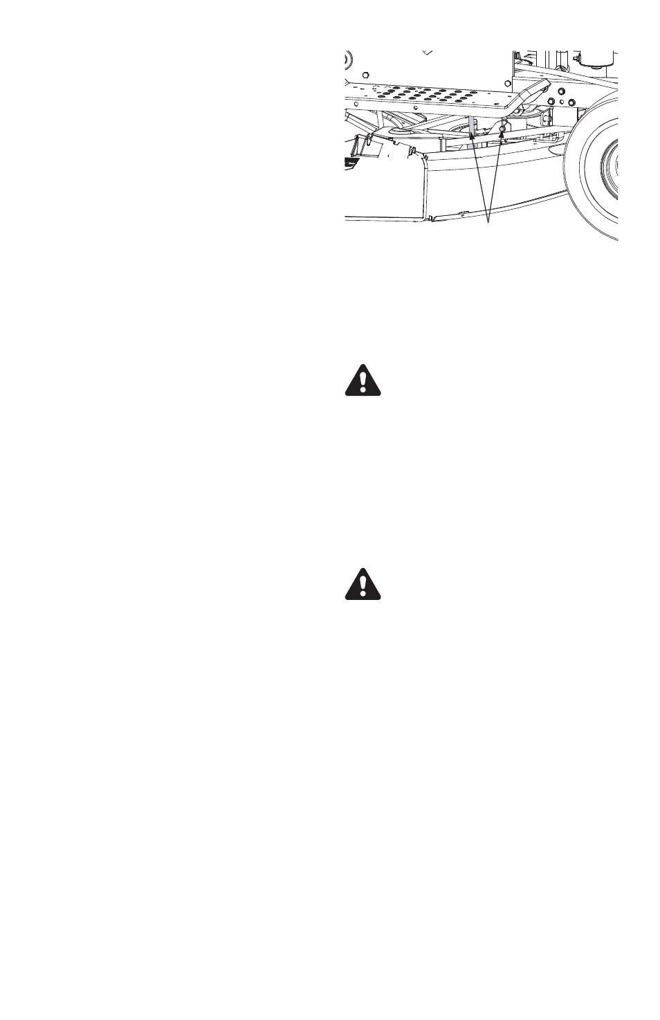
•
Remove the hairpin clip from the ferrule
found at the bottom of the front, left deck
link (hairpin clip is on the inside of the lift
link). See Figure 8 .
•
Pull the ferrule out of the deck hanger and
thread the ferrule up or down, as neces-
sary.
NOTE: Usually only one or two turns are
needed.
•
Insert the ferrule back into the deck hanger
and refasten with the hairpin clip removed
earlier.
•
Repeat the previous steps on the front,
right lift link
•
Check the front-to-rear adjustment by
re-measuring. Check the side-to-side ad-
justment by placing a level on the deck
surface.
•
Readjust if necessary.
SETTING THE DECK WHEEL HEIGHT (on
models so equipped)
•
Select the height position of the cutting
deck by placing the Deck Engagement /
Lift Lever in any of the five different cutting
height notches on the right side of the
frame.
•
Adjust the deck wheels so that they are
between 1/4-inch and ½-inch above the
ground when the tractor is on a smooth,
flat surface such as a driveway.
WARNING: Keep hands and feet
away from the discharge opening of
the cutting deck.
NOTE: The deck wheels, on models
so equipped, are an anti-scalp feature
of the deck and are not designed to
support the weight of the cutting deck.
Refer to Deck Leveling Adjustment of this
manual for more detailed instructions regard-
ing deck adjustments.
DECK ENGAGEMENT ADJUSTMENT
WARNING: Never attempt to make
the adjustment while the engine is
running. Always shift to neutral, set
the parking brake, stop engine and
remove key to prevent unintended
starting.
The cutting deck engagement may be ad-
justed to make certain the deck is
disengaged when deck engagement/lift lever
is in the BLADES STOP position. Correct ad-
justment as follows.
•
With the engine off, place the deck en-
gagement/lift lever in the BLADES OFF
position.
•
Unthread the shift knob and remove the
two flange screws which secure the shift
cover panel in place. See Figure 11.
•
Remove the cover panel and locate the
deck disengagement rod. See Figure 11.
NOTE: There is a small yellow wire
connected to a spring switch on the
underside of the cover panel. Be care-
ful not to damage it when removing
the panel.
15
FIGURE 8
Adjustable Deck Links,
Ferrules & Hairpin Clips