Cub Cadet C-155G User Manual
Page 16
•
Remove the hairpin clip which secures the
disengagement rod to the stabilizer shaft
assembly. See Figure 10.
•
Pull the rod toward the rear of the tractor
(to take up slack), then thread the rod in-
ward or outward (usually only one or two
turns) until the rod lines up as precisely as
possible with the hole in the stabilizer
shaft.
NOTE: Threading the disengagement
rod outward (toward the rear of the
tractor) provides for more belt tension.
Threading the disengagement rod in-
ward provides for less belt tension.
•
Reinsert the ferrule and re-secure the rod
with the cotter pin removed earlier.
Check the adjustment by placing the deck
engagement/ lift lever in the BLADES STOP
position. The deck should move up and for-
ward, allowing the belt to become loose.
•
Reassemble the cover panel.
•
Start the tractor’s engine and test the deck
engagement/lift lever to be certain the
blades fully disengage when in the
BLADES STOP.
•
Repeat the adjustment procedure if neces-
sary.
PARKING BRAKE ADJUSTMENT
WARNING: Never attempt to adjust the
brakes while the engine is running.
Always disengage PTO, move speed
control lever into neutral position, stop
engine and remove key to prevent
unintended starting.
If the tractor does not come to a complete stop
when the brake pedal is completely depressed,
or if the tractor’s rear wheels can roll with the
parking brake applied, the brake is in need of
adjustment. The brake disc can be found on the
right side of the transmission in the rear of
the tractor. Adjust if necessary as follows:
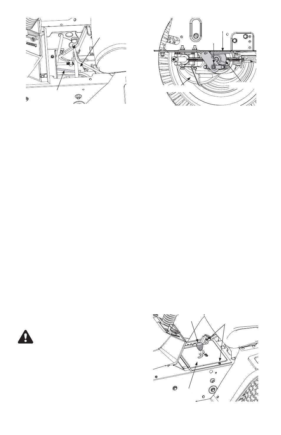
Looking at the transmission from the right side
of the tractor, locate the compression spring and
brake disc. See Figure 10.
•
Loosen, but do NOT remove, the hex nut
found on the right side of the brake assembly.
See Figure 10.
•
Using a feeler gauge, set the gap between
the brake disc and the brake puck at .011".
•
Re-tighten the hex nut loosened earlier.
SPEED CONTROL ADJUSTMENT
NOTE: When operating the unit initially
or after replacing the belts, there will
be little difference between the highest
two speeds until after the belts have
gone through a break-in period and
have seated themselves into the pul-
leys.
If the full range of speeds cannot be ob-
tained on your unit, adjust the speed control
as follows.
•
Unthread the shift knob and remove the
two flange screws which secure the cover
panel in place. Refer to Figure 11.
16
FIGURE 9
Disengagement Rod
Stabilizer Shaft
Assembly
R,
FIGURE 10
Compression
Spring
Hex
Nut
Brake Disc
Transmission
FIGURE 11
Flange Screws
Knob
Shift Cover Panel