Cub Cadet C-155G User Manual
Page 23
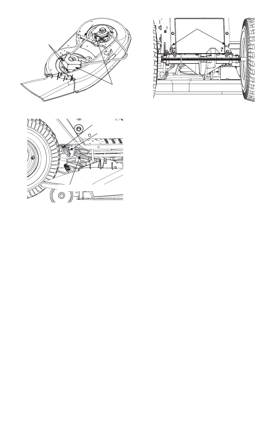
NOTE: On 46-inch decks, you must also re-
move both the deck stabilizer bracket and
the stabilizer rod. To do so, remove the hair-
pin clip which secures the stabilizer rod to
the stabilizer bracket. See Figure 25.
After the deck is removed (and the stabilizer
bracket and rod), the upper deck belt can be
simply lifted off of the double-pulley located
in the rear, center of the cutting deck.
To remove the lower deck belt:
•
Follow all steps above for removing the
upper deck belt.
•
Remove the belt guards (located over
each outer spindle pulley) by removing the
self-tapping screws which secure them in
place. Refer to Figure 24.
•
Using a spring puller (Part No. 732-0571)or
other suitable tool, disconnect the exten-
sion spring from the rear of the cutting
deck belt. This will relieve tension on the
lower deck belt.
•
Remove the lower deck belt from around
the idler pulleys, and the three spindle pul-
leys.
•
Reassemble new belts, following instruc-
tions in reverse order.
Drive Belts (Upper and Lower)
NOTE: The engine pulley must be removed
from the engine’s crankshaft in order to
change the tractor’s drive belts. Doing so re-
quires an air/impact wrench.
It is recommended that both belts be
changed at the same.
•
Place the deck engagement/lift lever in the
engaged (all the way forward) position.
•
Unthread the shift knob and remove the
two flange screws which secure the cover
panel in place. Refer to Figure 11. Remove
the cover panel.
NOTE: There is a small yellow wire con-
nected to a spring switch on the underside
of the cover panel. Be careful not to damage
it when removing the panel
•
Using a spring puller (Part No. 732-0571)or
other suitable tool, disconnect the spring
which is attached to a small hook found on
the left, rear portion of the transmission.
Refer to Figure 18.
•
Using a spring puller or other suitable tool,
disconnect the two springs which are at-
tached to the rear portion of the tractor
frame. See Figure 26.
•
Place the deck engagement/lift lever in the
BLADES STOP position.
•
Locate the two belt keeper pins, found on
either side of the engine pulley, and use a
1/4-inch socket wrench to remove them
from the lower frame. Refer to Figure 19.
NOTE: When reassembling, make cer-
tain belt keeper pins are assembled in
the same locations from which they
were removed.
•
Using an impact gun with a 5/8-inch
socket, remove the hex screw with secures
the engine pulley to the engine crankshaft.
23
FIGURE 25
Stabilizer Rod
Stabilizer Bracket
Hairpin Clip
FIGURE 26
Springs
FIGURE 24- 42-inch deck shown
Self-Tapping
Screws
Belt Guards