Cub Cadet C-155G User Manual
Page 17
•
Remove the cover panel and locate the
speed control rod. See Figure 14.
NOTE: There is a small yellow wire con-
nected to a spring switch on the underside of
the cover panel. Be careful not to damage it
when removing the panel.
•
Remove the hairpin clip which secures the
speed control rod’s ferrule to the speed
bracket. See Figure 14.
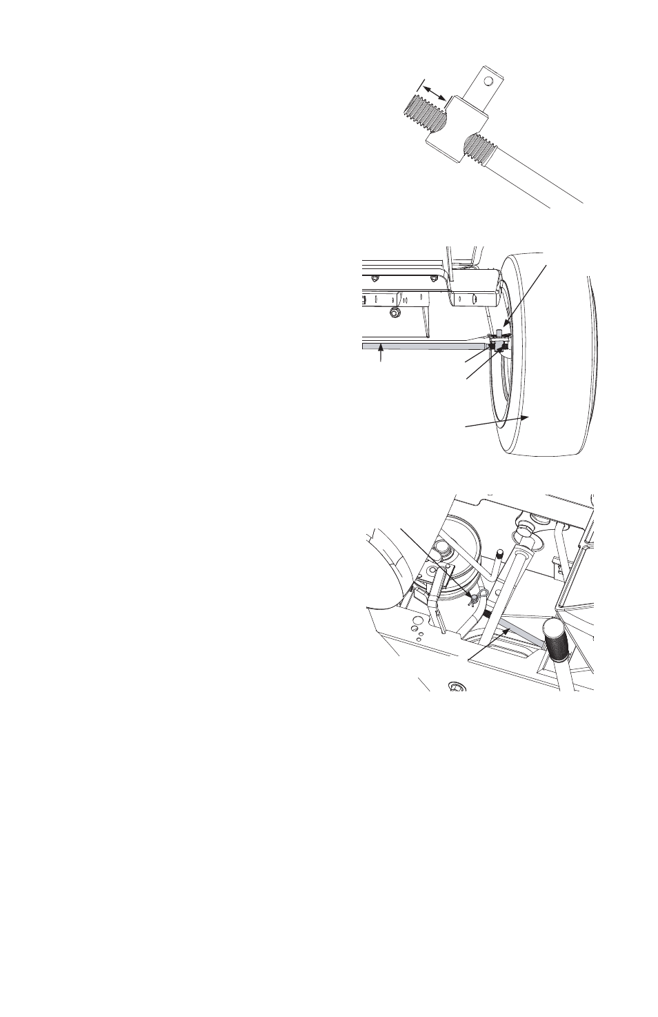
At the factory, the speed control rod is ad-
justed so that 5/8-in. of the rod is exposed
beyond the ferrule.
•
Adjust the speed control by threading the
ferrule inward so that no more than 3/4-in.
of the rod is exposed beyond the ferrule.
See Figure 12.
•
Reinsert the ferrule and re-secure the rod
with the hairpin clip removed earlier.
•
Reassemble the cover panel, start the trac-
tor’s engine and test the full range of
speeds.
IMPORTANT: If the above adjustment did
not result in the tractor obtaining the full
range of speeds, see an authorized service
dealer to have the variable speed drive sys-
tem inspected and professionally adjusted.
STEERING ADJUSTMENT
(Units With Adjustable Tie Rod)
If the tractor turns tighter in one direction
than the other, or if either the tie rod and fer-
rule are being replaced due to damage or
wear, the tie rod may need to be adjusted.
To do so, proceed as follows:
NOTE: A replacement cotter pin (part no.
714-0470) is needed to complete this adjust-
ment. Have one on hand before proceeding.
•
Place the steering wheel in position for
straight ahead travel.
•
In front of the pivot bar, measure the dis-
tance horizontally from the inside of the left
rim to the inside of the right rim. Note the
distance.
•
Behind the pivot bar, measure the distance
horizontally from the inside of the left rim
to the inside of the right rim. Note the dis-
tance.
•
The measurement taken in front of the
pivot bar should be between 1/16” and
5/16” less than the measurement taken be-
hind the pivot bar. If it is not, an
adjustment is necessary. Proceed as fol-
lows.
•
Locate the ferrule at the right end of the tie
rod, just to the rear of the right, front tire of
tractor. See Figure 13.
•
Remove the cotter pin and flat washer
which secures the adjustment ferrule to the
tractors right axle.
•
Two turns at a time, thread the adjustment
ferrule toward the right, front tire to
lengthen the tie rod. Or, thread the adjust-
ment ferrule away from the right, front tire
to shorten the tie rod.
NOTE: Lengthening the tie rod increases the
tractor’s front tie toe-in. Shortening the tie
rod decreases the tractor’s front tire toe-in.
•
Reinsert the adjustment ferrule and tempo-
rarily secure it with the cotter pin removed
earlier.
17
FIGURE 12
3/4"
Maximum
FIGURE 13
Ferrule
Tie Rod
Right Axle
Right Front Tire
Flat Washer
Cotter Pin
Right Front Tire
FIGURE 14
Speed Control Rod
Ferrule and
Hairpin Clip