Checkline TS2P User Manual
Page 6
– 6 –
3.0 OPERATING PROCEDURES
3.1 Mounting Arrangements
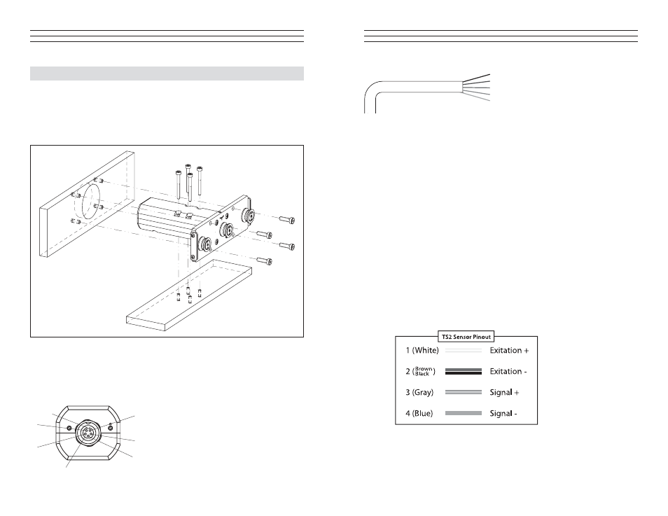
TS2 Series sensors can be mounted in different ways:
• Mounting by using the frontplate on a cylindrical hole (cut out 38.5 - 40 mm Ø)
• Mounting on a lat platform
M3 Screws
M4 Screws
3.2 Connector Assignment
NOTE: To assure immunity to random noise, the measuring head must be installed
so that it is insulated from ground (GND). The shield of the connecting cable must
be connected to the metal housing of the connecting plug.
Pin assignment viewed from outside:
1 - Vcc + 15 to 24 V DC regulated
2 - Ground
3 - Ground
4 - Signal output -
5 - Signal output +
1
3
Shield
2
5
4
Female socket M9
– 7 –
3.3 Options
Code DC Analog output 0 - 10 V DC
Code MA Analog output 4 - 20 mA
3.4 Initial Setup
• Install the sensor at the desired measuring location.
• Connect the sensor to the supplied or existing display unit. The pin assignment
of the 5-pin connector located on the rear side of the sensor is described in
section 3.2.
• If the material path is other than vertical or if the process material deviates
signiicantly from the factory calibration material, you need to carry out
ZERO Adjustment and GAIN Adjustment as described in sections 4.1 and
4.2 before starting measurement.
• Allow approx. 10 minutes for thermal stabilization of the sensor.
• Thread the process material through the measuring and guide rollers, following
the material path symbol on the front of the sensor.
1
2
3
4
5
Strand assignment of cable EK0620:
1 (white) Vcc + 15 to 24 V DC regulated
2 (black) Ground
3 (brown) Ground
4 (blue)
Signal output –
5 (grey)
Signal output +