Zero gain, Guide rollers 2x – Checkline TS2P User Manual
Page 5
– 5 –
Model
Tension
Ranges [g]
*Measuring Head
Width [mm]
**Factory
Calibration
Material
TS2L-50
0 - 50
150
PA: 0.12 mm Ø
TS2L-100
0 - 100
150
PA: 0.12 mm Ø
TS2L-200
0 - 200
150
PA: 0.12 mm Ø
TS2L-500
0 - 500
150
PA: 0.20 mm Ø
TS2L-1K
0 - 1000
150
PA: 0.30 mm Ø
V-Groove
Line Speed
[m/min ... max.]
Roller Material
Standard
4000
Hardcoated aluminium
Code T
4000
Plastic (PVC red)
(same dimensions as standard roller)
2.4 TS2L Models
2.5 T2B Models
Model
Tension
Ranges [g]
*Measuring Head
Width [mm]
Roller Widths
[mm]
TS2B-100
0 - 100
60
7, 10, 15, 20
TS2B-200
0 - 200
60
7, 10, 15, 20
TS2B-500
0 - 500
60
7, 10, 15, 20
TS2B-1K
0 - 1000
60
7, 10, 15, 20
TS2B-2K
0 - 2000
120
7, 10, 15, 20
TS2B-5K
0 - 5000
120
7, 10
V-Groove
Line Speed
[m/min ... max.]
Roller Material
Standard
1000
Hardcoated aluminium
(exception: 7 mm rollers are
made of nickel-plated steel)
*
Depending on model, either width of ilament guide or outer distance between outside
guide rollers.
**
Suitable for 95% of applications. PA = Polyamide Monoilament
Should the process material differ signiicant from the factory calibration material
in size, rigidity or shape, we recommend special calibration using customer supplied
material.
International unit of tensile force:
1 g
= 1.02 g
=
0.01 N
1 Kg
= 1.02 kg
= 10.00 N
TS2L Guide Rollers
TS2B1 Guide Rollers
– 8 –
4.0 INTERNAL ADJUSTMENT OF THE SENSORS
If the sensor has been delivered with a display unit, the ZERO and GAIN
adjustments should only be carried out with the supplied display unit.
All tension meters are calibrated with standard material, such as polyamide
monoilament (PA), according to the factory procedure; the material path is
vertical. Any difference in process material size and rigidity from the standard
material may cause a deviation of the accuracy.
In 95% of all industrial applications, the factory calibration has been proven to
provide the best results and is used for comparative purposes.
If required you can also operate the sensors with a material path other than vertical.
Should the process material differ signiicantly from the factory calibration material
in size, rigidity or shape, we recommend special calibration using customer
supplied material. If the material path is other than vertical or if the process
material deviates signiicantly from the factory calibration material, you need to
carry out static ZERO and GAIN adjustment as described in sections 4.1 and 4.2.
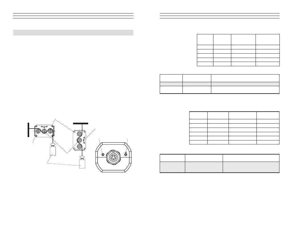
4.1 ZERO Adjustment
Mounting holes
4x
Weight
Material path symbol
Measuring
roller
Guide rollers 2x
ZERO
GAIN
1. Install the sensor in the desired position at the
measuring location using the provided mounting holes.
2. Allow approximately ten minutes for thermal stabilization of the sensor.
3. Thread the process material through the measuring and guide rollers, following
the material path symbol on the front of the sensor.