Checkline TS2P User Manual
Page 4
– 4 –
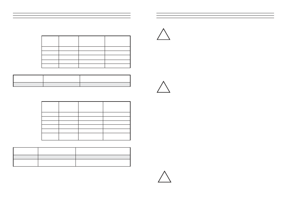
2.2 TS2P Models
2.3 TS2H Models
TS2P Guide Rollers
Model
Tension
Ranges [g]
*Measuring Head
Width [mm]
**Factory
Calibration
Material
TS2P-50
0 - 50
64
PA: 0.12 mm Ø
TS2P-100
0 - 100
64
PA: 0.12 mm Ø
TS2P-200
0 - 200
64
PA: 0.12 mm Ø
TS2P-500
0 - 500
64
PA: 0.20 mm Ø
TS2P-1K
0 - 1000
64
PA: 0.30 mm Ø
Ceramic Pins
Line Speed
[m/min ... max.]
Pin Material
Standard
2000
Oxid ceramic 5.2 mm Ø
TS2H Guide Rollers
Model
Tension
Ranges [g]
*Measuring Head
Width [mm]
**Factory
Calibration
Material
TS2H-1K
0 - 1000
150
PA: 0.30 mm Ø
TS2H-2K
0 - 2000
150
PA: 0.50 mm Ø
TS2H-5K
0 - 5000
150
PA: 0.80 mm Ø
TS2H-10K
0 - 10 Kg
200
PA: 1.00 mm Ø
TS2H-20K
0 - 20 Kg
240
PA: 1.50 mm Ø
TS2H-50K
0 - 50 Kg
240
Steel rope: 1.5mm Ø
(7 x 7 x 0.20)
V-Groove
Line Speed
[m/min ... max.]
Roller Material
Standard
4000
Hardened-steel roller
U-Groove
Code R1
4000
Hardened-steel roller (radius 5)
– 9 –
WARNING: When threading the process material through the rollers, follow
the material path symbol on the front of the sensor. If a force is applied to the
middle sensor roller in the incorrect direction, damage could result.
4. Install the sensor in the desired position at the measuring location using the
provided mounting holes.
5. Allow approximately ten minutes for thermal stabilization of the sensor.
6. Thread the process material through the measuring and guide rollers, following
the material path symbol on the front of the sensor.
WARNING: When threading the process material through the rollers, follow
the material path symbol on the front of the sensor. If a force is applied to
the middle sensor roller in the incorrect direction, damage could result.
NOTE: Since ZERO and GAIN adjustments are always performed
statically, the readings may differ under dynamic load.
7 Hang a weight that corresponds to e.g. 10% of the tension range from the
process material.
8. Connect a volt meter to pins 4 and 5 of the connector on the rear side of the
unit.
9. Adjust the potentiometer, which you can reach through the ZERO hole in the
housing, with a screwdriver (with a point width of max. 1.9 mm) until the
display of the connected volt meter reads,
for example:
Sensor model TS2 - 200:
Weight 20 g = Display 0.100 V for the TS2 standard version
or
Weight 20 g = Display 1.00 V for the TS2 version with 10 V output signal.
WARNING: Do not insert the screwdriver at an angle as this may damage
the potentiometer.
!
!
!