Checkline TS2P User Manual
Page 3
– 3 –
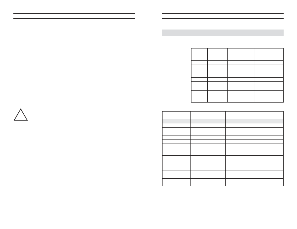
2.0 AVAILABLE MODELS
2.1 TS2 Models
Model
Tension
Ranges [g]
*Measuring Head
Width [mm]
**Factory
Calibration Material
TS2-50
0 - 50
64
PA: 0.12 mm Ø
TS2-100
0 - 100
64
PA: 0.12 mm Ø
TS2-200
0 - 200
64
PA: 0.12 mm Ø
TS2-500
0 - 500
64
PA: 0.20 mm Ø
TS2-1K
0 - 1000
64
PA: 0.30 mm Ø
TS2-2K
0 - 2000
124
PA: 0.50 mm Ø
TS2-5K
0 - 5000
124
PA: 0.80 mm Ø
TS2-10K
0 - 10 Kg
124
PA: 1.00 mm Ø
TS2-20K
0 - 20 Kg
224
PA: 1.50 mm Ø
TS2-50K
0 - 50 Kg
224
Steel rope: 1.5mm Ø
(7 x 7 x 0.20)
TS2 Guide Rollers
V-Groove
Line Speed
[m/min ... max.]
Roller Material
Standard
2000
Hardcoated aluminium
Code K
3500
Hardcoated aluminium
Code H
5000
Plasma-coated aluminium
(TS2-100 and higher ranges)
Code T
1000
Plastic (POM) black
Code W
1000
Nickel-plated steel
Code ST
1000
Hardened steel
Code B
1000
Tempered steel, specially for
measuring tire cord
Code CE1
1000
Ceramic
Asymmetrical
Groove
Code ASY
1000
Hardcoated aluminium
(TS2-500 and higher ranges)
Code ASYB
1000
Tempered Steel
(TS2-500 and higher ranges)
U-Groove
Code U
2000
Hardcoated aluminium
(TS2-500 and higher ranges)
*
Depending on model, either width of ilament guide or outer distance between outside
guide rollers.
**
Suitable for 95% of applications. PA = Polyamide Monoilament
Should the process material differ signiicant from the factory calibration material
in size, rigidity or shape, we recommend special calibration using customer supplied
material.
International unit of tensile force:
1 g
= 1.02 g
=
0.01 N
1 Kg
= 1.02 kg
= 10.00 N
–10 –
4.2 GAIN Adjustment
Requirement: ZERO adjustment carried out.
1. Thread the process material through the measuring and guide rollers, following
the material path symbol on the front of the sensor.
2. Hang a weight that corresponds to e.g. 95% of the tension range from the
process material.
3. Adjust the potentiometer, which you can reach through the GAIN hole in the
housing, with a screwdriver (with a point width of max. 1.9 mm) until the
display of the connected volt meter reads,
for example:
Sensor model TS2 - 200:
Weight 190 g = Display 0.950 V for TS2 standard version
or
Weight 190 g = Display 9.50 V for TS2 version with 10 V output signal.
WARNING: Do not insert the screwdriver at an angle as this may damage
the potentiometer.
4. Check the adjustments with a fresh portion of the process material and repeat
the procedure, if required, as described in Chapters 3.3.1 and 3.3.2.
!