Checkline TI-25M-MMX User Manual
Page 8
– 8 –
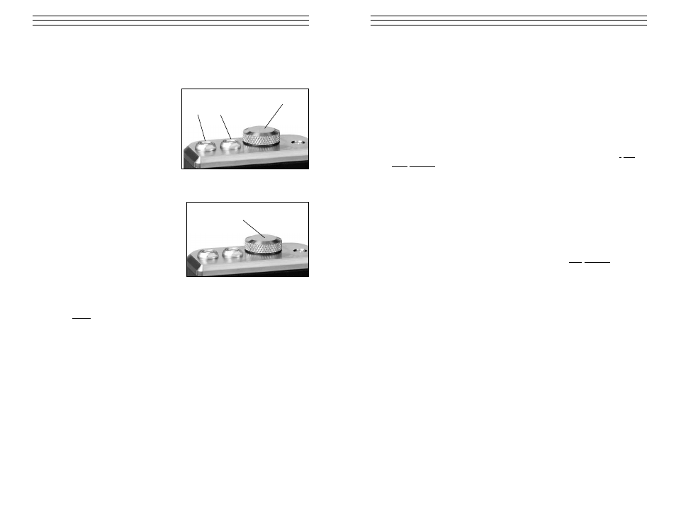
3.7 Probe Connector Receptacle
Located on the top edge of the TI-25M-MMX housing are the receptacles
for the probe and the probe zero plate.
The connectors for the probe
are non-polarized so the con-
nector at the end of the probe
cable can be inserted into
this receptacle in either
orientation. Make sure the
connector is “well seated” in
the receptacle.
3.8 Battery Compartment (Changing The Battery)
The battery compartment is
located under the probe zero
test plate. To open the battery
compartment, unscrew the
probe zero plate by rotating it
counterclockwise. The
TI-25M-MMX operates on
two (2) AA Batteries (1.5 V).
If desired, rechargeable
batteries may be used.
The TI-25M-MMX is shipped with the batteries installed. Insert batteries in
the polarity indicated on the rear label.
Note: When the display elements begin to flash off and on repeatedly, the
batteries are low and should be replaced.
Battery Cover
Probe Receptacles
Probe Zero
Plate
– 21 –
1 1 .0 CALI BRAT I ON FOR M EASU RI N G T H I CK N ESS OF
M AT ERI ALS OT H ER T H AN ST EEL
Ultrasonic Thickness Gauges use sound waves to measure wall thickness.
Different types of materials have different inherent acoustic velocities. For
instance, the acoustic velocity of steel is 0.2330 IN/µs (inches-per-microsecond),
versus that of aluminum, which is about 0.2500 IN/µs. It is critical that the
TI-25M-MMX be set for the correct acoustic velocity depending upon the materi-
al to be measured.
The TI-25M-MMX is shipped from the factory calibrated for steel with an
acoustic velocity of 0.2330 IN/µs (5920 M/s). To measure the thickness of any
other material, the calibration will have to be changed by adjusting the acoustic
velocity to the appropriate value for the specific material being measured.
To determine the proper acoustic velocity for the non-steel material, refer to the
Acoustic Velocity Table, section 10.1. After determining the proper acoustic
velocity, the gauge must be re-calibrated for this new value.
If you do not know the type of material to be measured or if the material type is
not listed in the Acoustic Velocity Table follow the following procedure.
11.1 Changing Calibration - Acoustic Velocity Is Not Known
In applications where the type of material is not known or the material is
not listed in the Acoustic Velocity Table, the following procedure can be
used to calibrate the gauge for highest accuracy.
1. Obtain a sample of the material with a known thickness or use a
micrometer, caliper or similar device to accurately measure it.
2. Turn on the gauge by pressing the ON/OFF key.
3. Place a small amount of coupling fluid on the sample of known
thickness and place the probe on the sample. The Stability Indicator
should have nearly all its bars illuminated. Having achieved a stable
reading remove the probe from the sample.
4. Press the CAL key.
5. The units of measure indicator “IN” or “MM” will be flashing
indicating that you are in the Measurement Calibration mode.
6. Use the UP and DOWN arrow keys to adjust the displayed measurement
value to match the thickness of the known sample. By pressing and
holding the key, the numbers will change more rapidly.