Operation – Checkline ESMH User Manual
Page 6
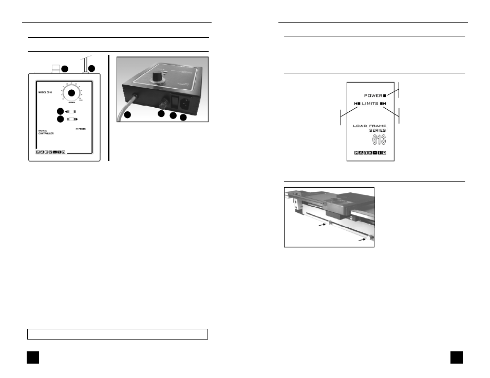
OPERATION
Using the controller
Model ESMH Motorized Test Stand
5
Note:
To maintain smooth functioning of the stand, avoid overloads.
4
5
6
Rear View
2
3
1
Top View
7
7
4
1. SPEED CONTROL DIAL
Adjust speed by turning the dial 0.2 – 50.0 in/min [5 – 1270 mm/min].
2. LEFT
Press and hold to move the crosshead to the left, producing compressive force.
Release button to stop motion.
3. RIGHT
Press and hold to move the crosshead to the right, producing tensile force. Release
button to stop motion.
4. CONTROLLER CABLE
Plug this cable into the lower connector on the test stand, adjacent to the motor.
5. POWER SWITCH
Use this switch to turn on and turn off power to the load frame. Power is indicated
by illuminated indicators on the face of the controller and load frame.
6. POWER PLUG RECEPTACLE
Plug the power cord in here.
7. FUSE
1.2 A, 250V, 3AG SLO BLO
User’s Guide
6
Using the limit switches
Limit switches are included to
allow the operator to set travel
limits during testing. This feature
is particularly useful for spring
testing, elongation testing, and
other applications where stopping
at a predetermined position is a
requirement.
The limit switches are located in
the rear of the load frame. Their positions can be adjusted by loosening
the thumbscrews (shown at left), sliding them to either side, and re-
tightening. During testing, when a travel limit has been reached, an
indicator will be illuminated (see illustration above) and the crosshead
movement will stop.
Reading the indicators
LEFT LIMIT
Indicates a limit condition
in compression.
RIGHT LIMIT
Indicates a limit condition in
tension.
POWER
Power is indicated by an
illuminated indicator.
Powering up
Plug the power cord into the controller and the other end into a wall
outlet. Then turn on power with the power switch (see Page 5).