Specifications – Checkline ESMH User Manual
Page 5
Model ESMH Motorized Test Stand
SPECIFICATIONS
Load capacity:
50 lb [250 N]
Speed range:
0.2-50 in/min [5-1270 mm/min]
Speed accuracy:
±5% of setting, ±0% variation with load
Maximum travel:
13.0 in [330.2 mm]
Maximum travel w/travel display:
12.0 in [304.8 mm]
Power:
Universal input 80-240 VAC, 50/60 Hz
Fuse type:
1.2 A, 250V, 3AG SLO BLO
Weight (test stand only):
17 lb [7.7 kg]
Controller weight:
2.7 lb [1.2 kg]
7
About the digital travel display (optional)
The travel display covers 12” of travel with a 5-
digit display (0.0005” resolution) and a computer
interface for automated data collection. Use ca-
ble P/N 09-1066 to output data to a PC.
Complete instructions are provided in a separate
user’s guide (included with the digital travel dis-
play).
User’s Guide
4
Mounting force gauges
To mount a force gauge, it is necessary
to temporarily remove the gauge
adapter from the crosshead. Loosen the
two 5/16 screws (shown at left) using
the included tool kit. Then, mount the
gauge to the adapter using the four in-
cluded gauge mounting screws. After
the gauge is mounted to the adapter,
mount the adapter back onto the cross-
head with the 5/16 screws.
Mounting grips and fixtures
The ESMH includes a loading plate to
which a grip or fixture may be mounted.
This plate can be mounted to the end of
the stand with four screws (shown at
left). Before mounting the loading plate,
mount the grip or fixture to it, using the
matrix of tapped holes if required.
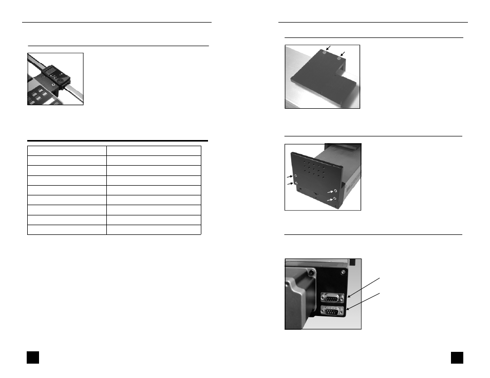
Setting up the controller
Plug the controller cable into the 9-pin male connector located beside
the motor. See illustration below.
Connector for optional set point cable /
overload protection module
Connector for controller