Specifications – Checkline TSFM500 User Manual
Page 6
Series TSF
The gauge bracket’s height can be adjusted along the column. Loosen
the four screws that secure the bracket to the column, adjust to the
desired height, and retighten the screws.
Note: To maintain smooth operation of the test stand, avoid overloads
and repetitive shock loads.
Optional Equipment
Digital Travel Display Kit
This travel indicator has a 5-digit display (0.0005” [0.01 mm] resolution)
and a computer interface for automated data collection. If purchased at
the same time as the test stand, no setup is needed. Otherwise, it may
be easily installed by the user.
Limit Switches
Adjust the switches’ vertical positions by loosening and re-tightening
the wing screws. A limit condition is indicated by an amber light on the
front surface of each sensor.
Upper limit switch – while a limit condition exists, the slider will not
move up
Lower limit switch – while a limit condition exists, the slider will not
move
down
Using the Control Unit
UP
Press and hold for tension, release button to stop motion. Located on
the face of the Control Unit.
DOWN
Press and hold for compression, release button to stop motion. Located
on the face of the Control Unit.
SPEED CONTROL DIAL
Adjust speed by turning the dial 0.2 – 5.5 in/min [5 – 140 mm/min]. Lo-
cated on the face of the Control Unit.
POWER SWITCH
Use this switch, in the left rear of the Control Unit, to turn on and turn
off power to the test stand. Power is indicated by an amber light on the
face of the Control Unit.
TSFM500 / TSFM500H
5
User’s Guide
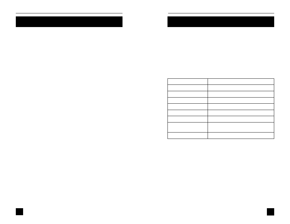
SPECIFICATIONS
Load capacity
500 lbF [2.2 kN]
Speed range
0.2 - 5.5 in/min [5 - 140 mm/min]
Maximum travel
4” [102 mm]
Speed variation with load ±0% (Stepper motor driven)
Power
Universal input, 80 - 240 VAC, 50/60 Hz
Fuse type
1.2A, 250V, 3AG SLO BLO
Weight (test stand only)
TSFM500: 36 lb [16.3 kg]
TSFM500H: 30 lb [13.6 kg]
Control unit weight
2.7 lb [1.2 kg]
Speed accuracy
±5% of setting
TSFM500 / TSFM500H
POWER PLUG RECEPTACLE
Located in the left rear of the Control Unit. Plug the power cord in here.
CONTROL CABLE
Plug this cable into the lower male connector on the test stand, adja-
cent to the motor.
6