Dimensions, Operation, Series tsf – Checkline TSFM500 User Manual
Page 5: User’s guide, Tsfm500h, Tsfm500
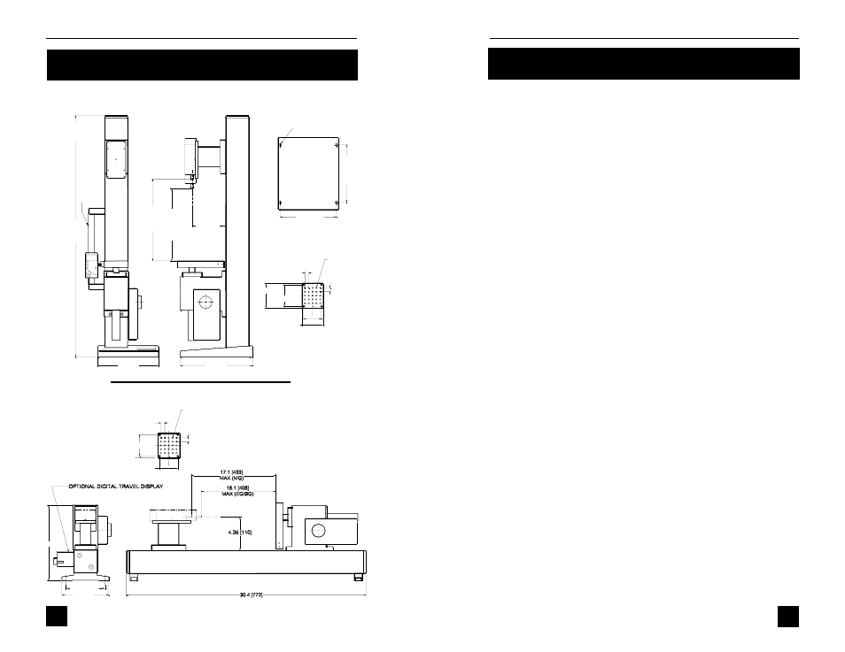
Series TSF
IN [MM]
10.0 [254]
6.0 [152]
5.00 [127.0]
MOUNTING PLATE
TOP VIEW
2.80 [71.1]
#10-32 UNF-2B
X 0.36 DEEP
X25
0.50 [12.7]
TYP
2.30 [58.4]
0.50 [12.7]
TYP
TSFM500 / TSFM500H
TSFM500H
7
2.76 [70.1]
3
1
.5
[
8
0
0
]
9.4 [239]
7.9 [201]
IN [MM]
MOUNTING PLATE
TOP VIEW
5/16-18 UNC-2B
X 0.600 [15.2] DEEP
X4
1
4
.5
[
3
7
4
]
M
A
X
(
M
G
)
1
3
.5
[
3
4
3
]
M
A
X
(
E
G
/B
G
)
4.35 [110]
0.500 [12.7]
TYP
#10-32 UNF-2B
X 0.360 DEEP
X25
O
P
T
IO
N
A
L
D
IG
IT
A
L
T
R
A
V
E
L
D
IS
P
L
A
Y
7
.5
0
[
1
9
0
.5
]
3.26 [82.8]
2.800 [71.1]
2.300 [58.4]
0.500 [12.7]
TYP
BASE PLATE
BOTTOM VIEW
7.30 [185.4]
DIMENSIONS
TSFM500
User’s Guide
TSFM500 / TSFM500H
With the base removed, the test stand can be easily integrated into
large systems such as production lines. In general, the stand can be
mounted on any angle (upside down, for example), although extra care
should be taken during installation and operation.
After the stand is in a stable and secure position, install a force gauge
with four thumb screws (provided). All Mark-10 gauges mount directly
without adapters.
Plug the control unit cable into the 9-pin male connector located above
the motor in the rear of the stand.
Plug the power cord into the remote console and the other end into a
wall outlet.
Turn on the power with the switch located on the control unit beside the
power cord.
The test stand is now ready for operation.
OPERATION
1. Mount the test stand to a firm, flat, and level working surface for
maximum safety and accuracy using four 5/16 screws (not in-
cluded). Use the included mounting hole drill template to accurately
drill the holes. Testing can take place without securing the test stand
in such a manner, however, it is strongly recommended that the
stand be secured.
2. Install a force gauge onto the gauge plate with four thumb screws.
All Mark-10 force gauges mount directly to the stand without adapt-
ers.
3. Install any required attachments, including grips, adapters, and
other materials necessary for your test sample. Make sure these
items are set up in a secure and safe manner.
4. Power on the control unit (further instructions to follow). For fine
adjustment or otherwise manual testing, turn the knob on the right
hand side of the stand clockwise for compression, counterclockwise
for tension.
4