Checkline Series-2 User Manual
Page 6
Series 2 Digital Force Gauges
User’s Guide
5
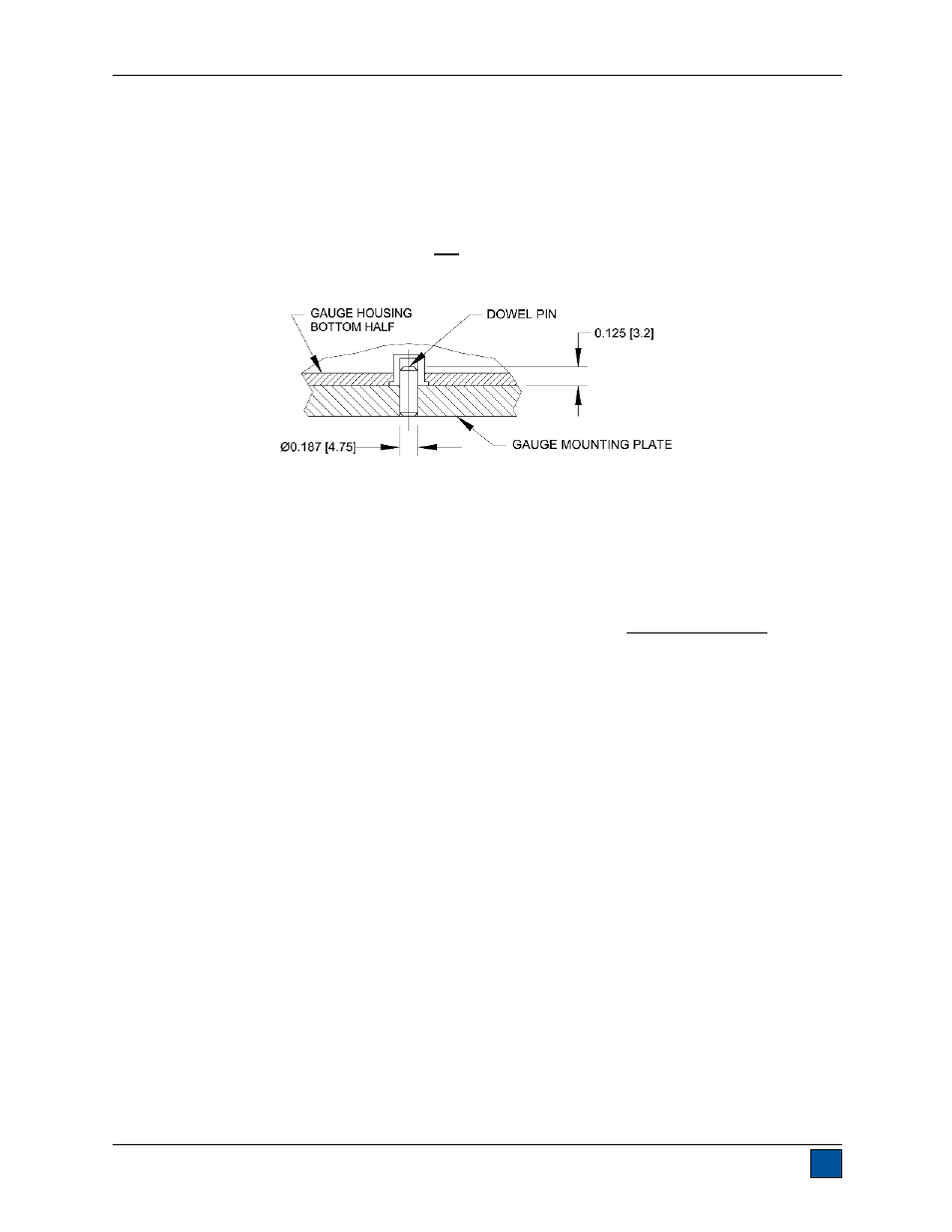
3.2 Mounting to a plate
Although the gauge may be used by hand, proper mounting is important if attached to a fixture or test
stand. The round steel insert with a hole in the back of the housing is provided to withstand the load
during a test. A mating dowel pin should be used (see illustration below). Mounting plates on Mark-10 test
stands include a dowel pin and clearance holes for the four threaded holes located near the corners of
the housing. An additional two holes are supplied for metric screws. These holes are designed to
accommodate screws in order to hold the gauge in place (Mark-10 test stands include a set of thumb
screws for gauge mounting). The screws must not be used for load bearing purposes. Failure to use a
dowel pin properly can result in a hazardous situation.
3.3 Mounting attachments to the gauge
The force gauge’s threaded loading shaft is designed to accommodate common grips and attachments
with female mounting holes. To mount a grip, gently thread it onto the shaft. Ensure that the grip or fixture
is positioned to ensure axial load with respect to the loading shaft of the force gauge. When using a grip,
ensure that it secures the sample in such a way that it is prevented from slipping out during a test,
preventing a potential safety risk to the operator and others in the vicinity. If using a grip or fixture from a
supplier other than Mark-10, ensure that it is constructed of suitably rugged materials and components.
Do not use jam nuts or tools to tighten grips or attachments onto the shaft. Finger-tighten only.