Notice – BUCHI UV-Vis Detector C-640 User Manual
Page 34
6 Maintenance and repairs
34
C-640 Operation Manual, Version A
Note
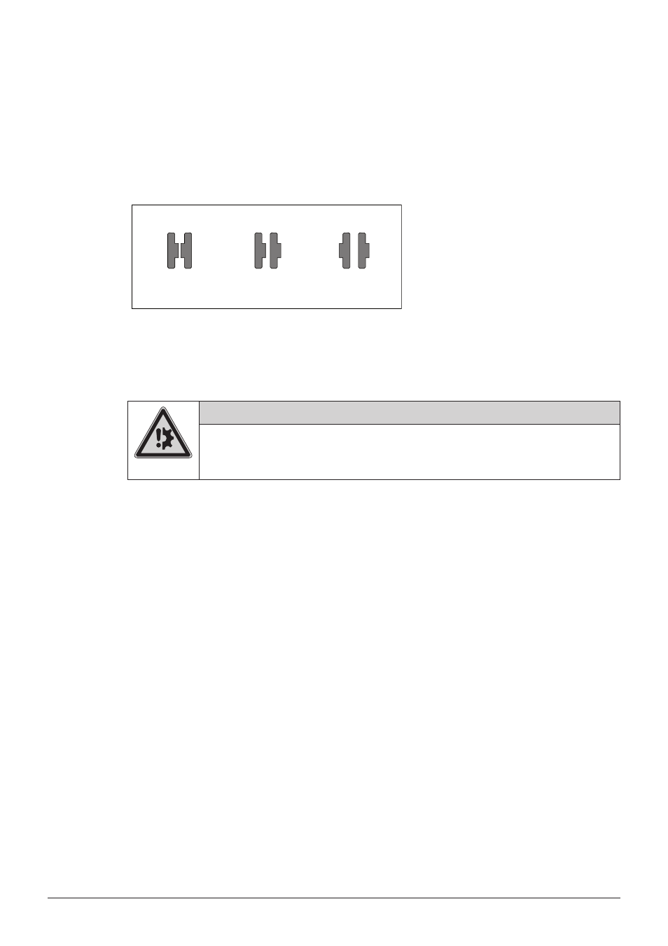
To change the thickness of the liquid layer (the optical path) between the two cell windows, one or
both windows can be reassembled in a different orientation. (See Figure 6-2)
By default the optical path through the cell window is adapted to 0.3 mm according to schema
a
in figure 6-2. For samples with lower concentration the length of the optical path can be increased
according to schema
b and c.
0.1 - 0.4 mm 1.1 - 1.4 mm 2.1 - 2.4 mm
a) b) c)
Figure 6-2: Adjustment of the optical path
After assembly, carefully tighten the screws crosswise using a watchmaker’s screwdriver.
Notice
Risk of instrument damage by wrong handling.
• Do not use too much force while tightening the screws - otherwise the cell windows may
break! Only use a watchmaker’s screwdriver which does not allow a too high momentum.
Before installing the reassembled cell to the cell compartment carefully check the cell for any impurities
(dust, hairs) using a magnifier. (Any impurity within the cell will increase the signal noise.)
After installing the cell into the cell compartment perform a leakage test.