4description of function – BUCHI UV-Vis Detector C-640 User Manual
Page 18
4 Description of function
18
C-640 Operation Manual, Version A
4
Description of function
This chapter explains the basic working principle of the UV-VIS Detector C-640. It also shows how the
instrument is structured and provides a general functional description of its assembly.
4 .1
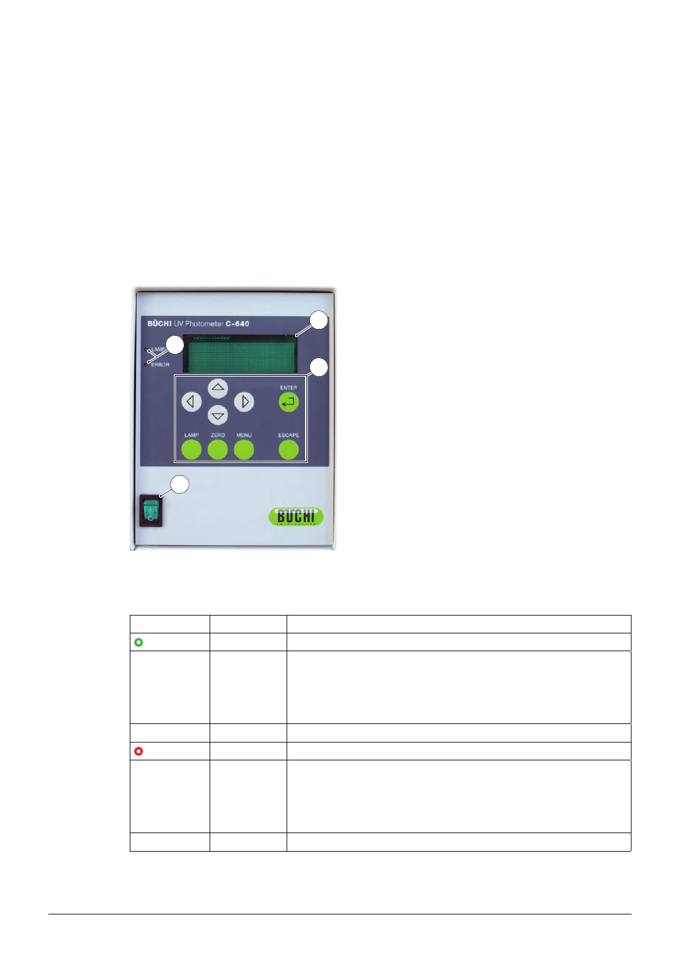
Front panel of the instrument
The front panel of the instrument consists of nine push buttons , two LED indicators b the ON /
OFF switch a and the graphical display .
1
4
2
3
a Power switch ON / OFF
b LED indicators (Lamp = green and Error = red)
Push buttons for operating the instrument
Graphical display
Figure 4-1: Front panel of the instrument
4 .1 .1
LED status
LED
LED status
Description
LAMP
Off
The detector-lamp is off.
On
The lamp is on.
NOTE
During start-up of the detector all LEDs will be switched on for a
short period of time.
Blinking
The detector-lamp is starting up.
ERROR
Off
The detector has no error.
On
An error occurred.
NOTE
During start-up of the detector all LEDs will be switched on for a
short period of time.
Blinking
Indicates a display error.