BUCHI Syncor Polyvap User Manual
Page 25
Syncore Platform
25
5.8 Signal-outputs
The Syncore platform is equipped with various signal outlets
that significantly extend the functionality of the unit. There are
two 24 V valve signal outlets. One is temperature-controlled,
the second is controlled by the ending of a program.
These signal outlets can be used with the corresponding
valves to:
• To control the flow of a cooling liquid through the cooling
plate in dependence upon the temperature. This facility is
employed when the reaction temperatures are less than
room temperature
• To control the flow of a cooling liquid through the conden-
ser unit in dependence upon the end of the program. This
facility is employed in the case of unattended evaporation
overnight with automatic termination of water flow once
the end of the program has been reached.
Only the valve recommended by BÜCHI Labortechnik AG
should be connected to the signal outlet.
Connection of valve on the socket TC
The signal outlet with a temperature-controlled or a tempe-
rature-dependent signal has been identified with a TC (for
tempe rature control).
The valve operates as follows: Hysteresis: 0.5°C.
• If the control temperature is lower than the actual tempe-
rature; the valve is open. Cooling liquid from an external
cooling system flows through the cooling plate
• If the control temperature is equal to or greater than the
actual temperature; the valve is closed. Cooling liquid from
an external cooling system no longer flows through the
cooling plate.
Connection of valve on the socket EC
The signal outlet for a signal sent after the end of a
program, after a manual stop, or after the direct ending of
a program via the „STOP“ button is labelled „EC“ (for End
Control).
After a (user-)defined after-running time has elapsed (follo-
wing the pressing of the „STOP“ button or after the end of
the program), the unit sends the signal to the external valve.
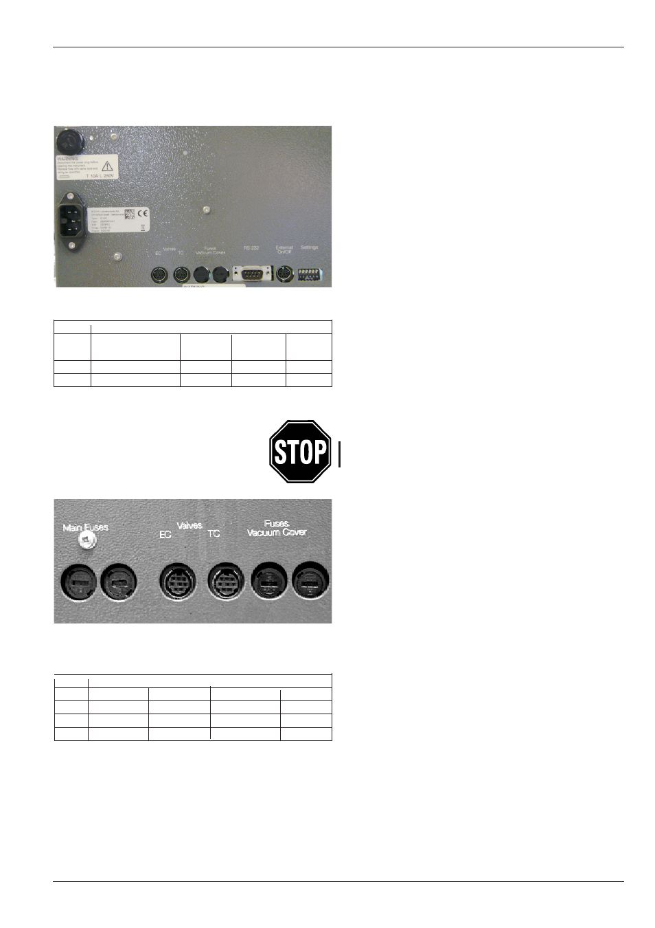
Figure 17: Signal-outputs and fuses with the corresponding order
number qty 10) for the new Syncore setup.
F4 F5
F1
Fuse 100 - 120 V
220 - 240 V
F1
15.0 AT (100 V)
051497
10.0 AT
016952
16.0 AT (120 V) 041859
F4
3.15 AT
019659
3.15 AT
019659
F5
3.15 AT
019659
3.15 AT
019659
Figure 18: Signal-outputs and fuses with the corresponding order
number (qty 10) for the original Syncore setup.
F1
F2
F4
F5
Fuse 100 - 120 V
220 - 240 V
F1
8.0 AT
022562
4.0 AT
016953
F2
8.0 AT
022562
4.0 AT
016963
F4
3.15 AT
019659
3.15 AT
019659
F5
3.15 AT
019659
3.15 AT
019659
5 Operation