Aviom AN-16/o User Manual
Page 36
28
AN-16/
o
o
utput
M
odule
u
ser
G
uide
To connect a 64 channel digital snake:
On the Send side:
Connect a Cat‑5e cable from the
1.
A-N
et
o
ut
of the first
AN‑16/i to port A on the first System Bridge.
Repeat this process to connect the A‑Net Out from the
2.
remaining three input modules to ports B, C, and D.
On the Receive side:
Connect a Cat‑5e cable from port A on the second System
1.
Bridge to the A-N
et
i
N
jack on the first AN‑16/o Output
Module.
Repeat this process to connect ports B, C, and D to the
2.
remaining AN‑16/o Output Modules.
Connect the two sides of the digital snake by running
3.
a Cat‑5e cable (with or without an EtherCon connector)
between the two A-N
et
B
ridge
jacks on the System Bridges.
P
N
ote
: Any combination of line‑level AN‑16/i and mic‑level AN‑16/i‑M
Input Modules can be substituted in the example above. Console
interface cards such as the Y1 or those offered by third‑party
manufacturers can be substituted for input modules shown in the
diagrams.
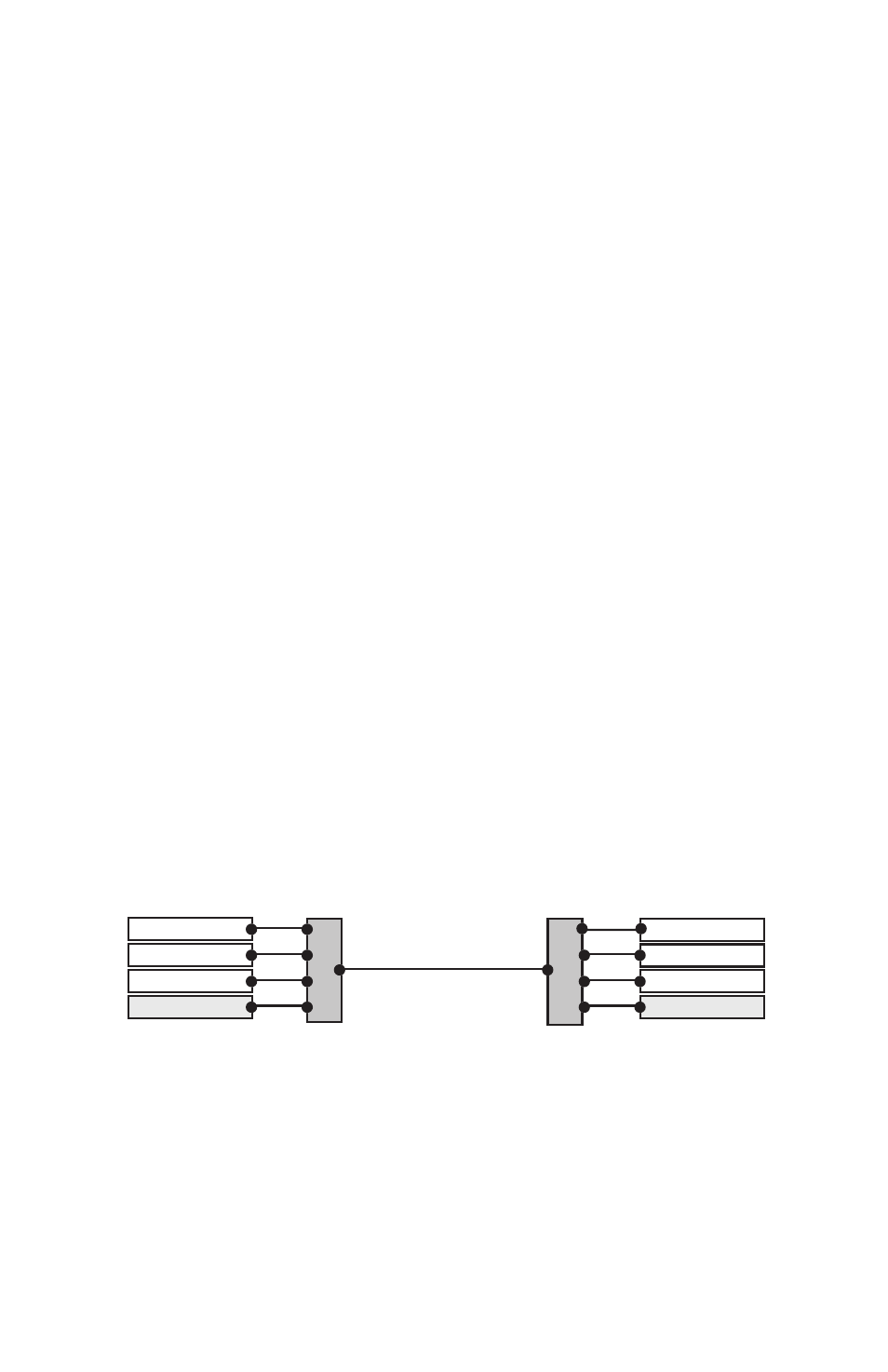
To use other configurations, simply move any pair of input and output
modules. In the following example, the devices connected to port D on the
System Bridge have been swapped to create a 48 x 16 system.
AN-16/i
AN-16/i
AN-16/i
AN-16/o
AN-16/o
AN-16/o
AN-16/o
AN-16/i
A-Net Out
A-Net In
A
B
C
D
A
B
C
D
Bridge
System Bridge
System Bridge
A 48 x 16 system is created by exchanging the units connected to port D on
the System Bridge.
Remember, the total cable length between A‑Net devices should not exceed
500 feet, 150 meters. Cables used to connect A‑Net devices to the System
Bridge are included in this calculation.