Connecting the system bridge – Aviom AN-16/o User Manual
Page 35
27
AN-16/
o
o
utput
M
odule
u
ser
G
uide
The System Bridge contains four A‑Net connectors labeled A, B, C, and D.
These accept standard Cat‑5e cables. These jacks will always connect to an
Pro16 A‑Net compatible product.
The connection labeled A-Net Bridge will always connect to another System
Bridge’s A‑Net Bridge connector.
Connecting the System Bridge
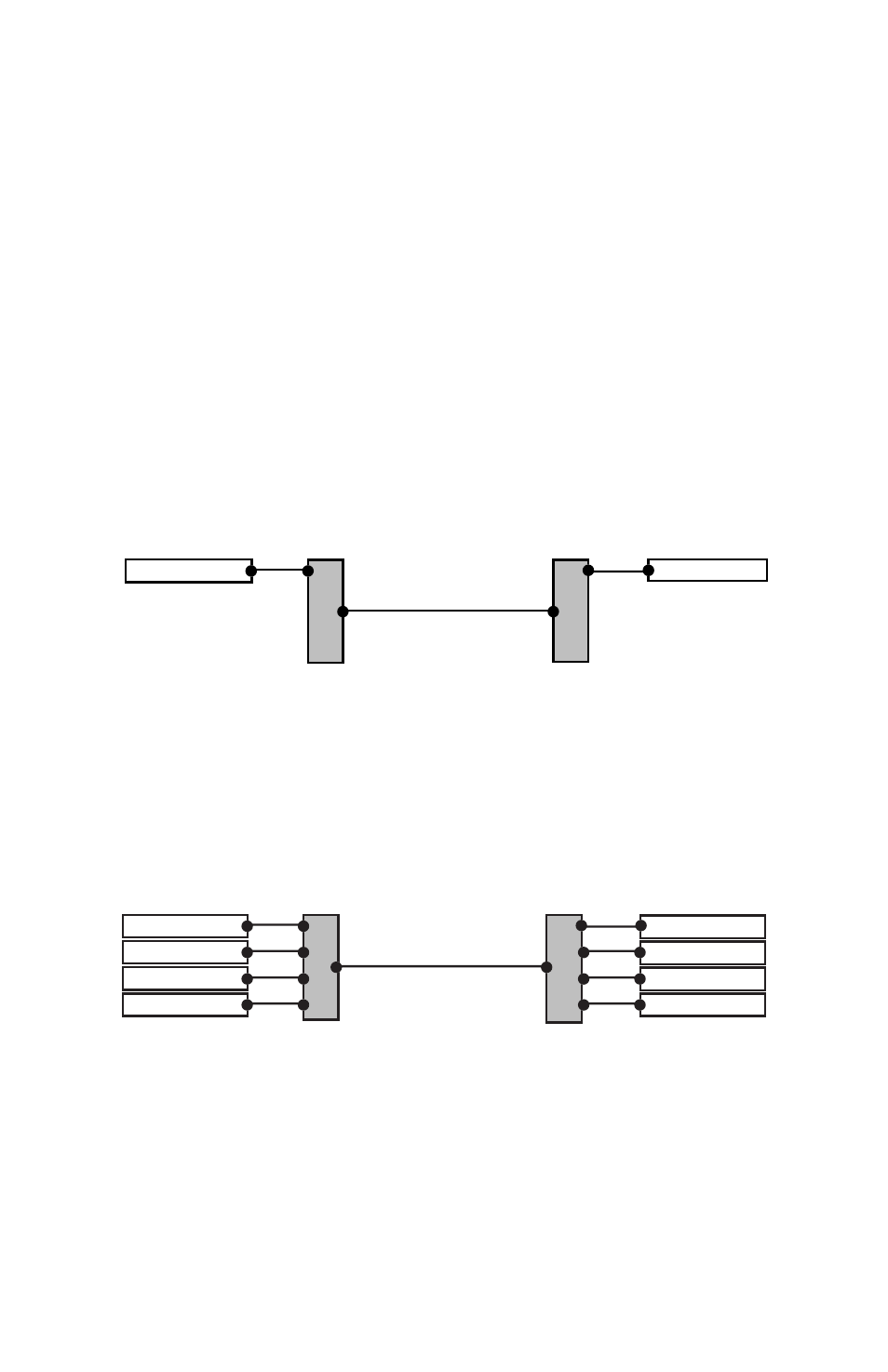
Adding a System Bridge to a digital snake is quite simple. Two System Bridges
are needed to create a network. The four A‑Net connectors (labeled A, B,
C, and D) on one side of the digital snake are directly related to the A, B, C,
and D connectors on the other side of the digital snake. That is, if you patch
an AN‑16/i Input Module into port “A” on one side of a System Bridge, an
AN‑16/o Output Module would be connected to port “A” on the other side of
the System Bridge. See the following diagram.
AN-16/i
AN-16/o
A-Net Out
A-Net In
A
B
C
D
A
B
C
D
Bridge
System Bridge
System Bridge
This diagram shows the relationship of the A, B, C, and D ports on the AN-16SB.
A complete digital snake using four units per side follows the same pattern.
An input module connected to port B on one side of the digital snake
connects to an output module via port B on the other side of the digital
snake. The same goes for ports C and D, as seen in the following diagram.
AN-16/i
AN-16/i
AN-16/i
AN-16/i
AN-16/o
AN-16/o
AN-16/o
AN-16/o
AN-16SB
AN-16SB
A-Net Out
A-Net In
A
B
C
D
A
B
C
D
Bridge
A-Net ports A, B, C, and D are shown connected in a 64 x 0 configuration