Carrier 40RU User Manual
Page 12
12
Unit Positioning -- The unit can be mounted on the floor for
vertical application with return air entering the face of the
unit and supply air discharging vertically through the top of
the unit. The unit can also be applied in a horizontal
arrangement with return air entering horizontally and the
supply air discharging horizontally. When applying the unit
in a horizontal arrangement, ensure the condensate drain pan
is located at the bottom center of the unit for adequate
condensate disposal. See Fig. 6 for condensate connections
for each unit position.
IMPORTANT: Do NOT attempt to install unit with return
air entering top panel of unit. Condensate will not drain from
unit.
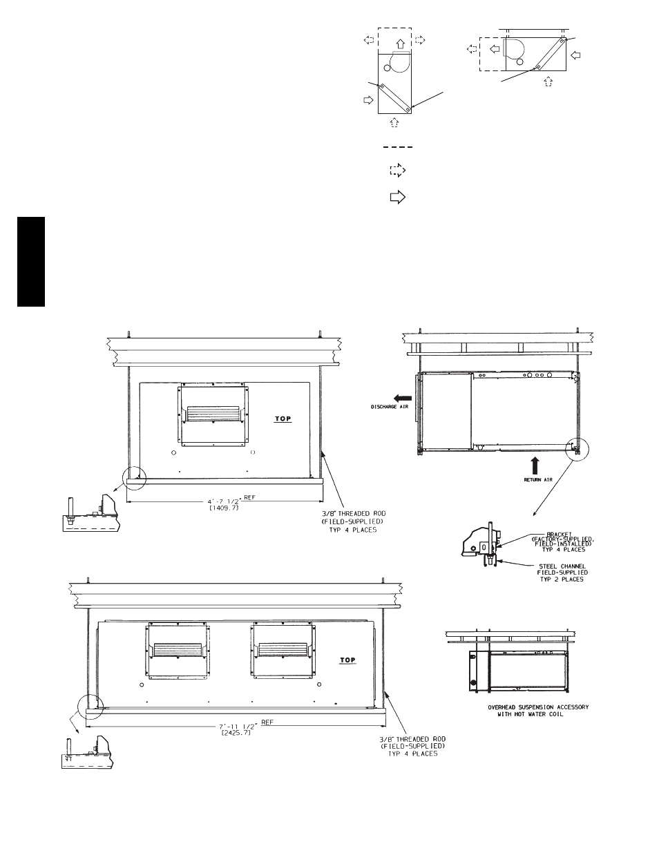
Typical positioning and alternate return air locations are
shown in Fig. 6. Alternate return air locations can be used
by moving the unit panel from the alternate return air
location to the standard return air location. Refer to overhead
suspension accessory drawing (Fig. 7) for preferred
suspension technique. The unit needs support underneath to
prevent sagging.
LEGEND
Accessory Line
Alternate Air Intake and Discharge
Air Intake and Discharge
Note: Maintain recommended clearances
per Fig. 1 and Fig. 2
PLUG
PLUG
CONDENSATE
DRAIN
C10684
Fig. 6 -- Typical Unit Positioning
UNIT SIZES 07 - 12
NOTE: Dimensions in [
] are millimeters.
OVERHEAD SUSPENSION ACCESSORY
UNIT SIZES 14 - 16
C10685
Fig. 7 -- Preferred Suspension Technique
40RU