Component location 2-pole indoor/outdoor – Steffes Transceiver User Manual
Page 7
4
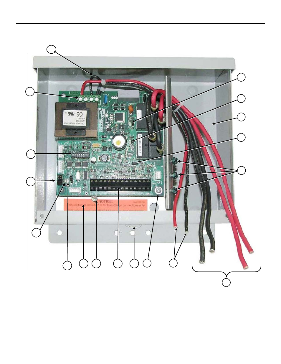
COMPONENT LOCATION 2-POLE INDOOR/OUTDOOR
Use this illustration to familiarize yourself with the location of parts you will use as the transceiver is installed,
set up, and its operation checked. The 2-pole transceiver shown is an outdoor enclosure; however, all
components are located in relatively the same locations in the indoor enclosure.
1 - Line Voltage Tapping [Page 10]
10 - Security Lockout/Seal Loop
2 - Relay #1 LED (marked "Relay 1") [Page 17]
11 - Low Voltage Terminal Block [Page 13]
3 - Relay #2 LED (marked "Relay 2") [Page 17]
12 - Temperature Sensing Thermistor [Page 13]
4 - Line Voltage Connection Area [Page 24]
13 - Low Voltage Connection Area [Page 13]
5 - Transmit/Receive Jumper ("TR/RC") [Page 13]
14 - Outside Temperature Indicator LED ("L3") [Page 17]
6 - SecureGround™ Ground Bond Screw [Page 10]
15 - PLC Signal Indicator LED ("L4") [Page 17]
7 - Supply Conductors (from circuit breaker panel) [Page 9] 16 - DIP Switches [Page 14-15]
8 - PCB Line Voltage Conductor “Control Circuit” [Page 9]
17 - Line Voltage Terminal Block [Page 9]
9 - Low Voltage Ground Screw
18 - THER Jumpers – Must be ON for all Transceivers
2
3
16
18
4
17
5
6
7
8
9
13
14
11
12
10
1
15