Line voltage connections 2-pole – Steffes Transceiver User Manual
Page 13
10
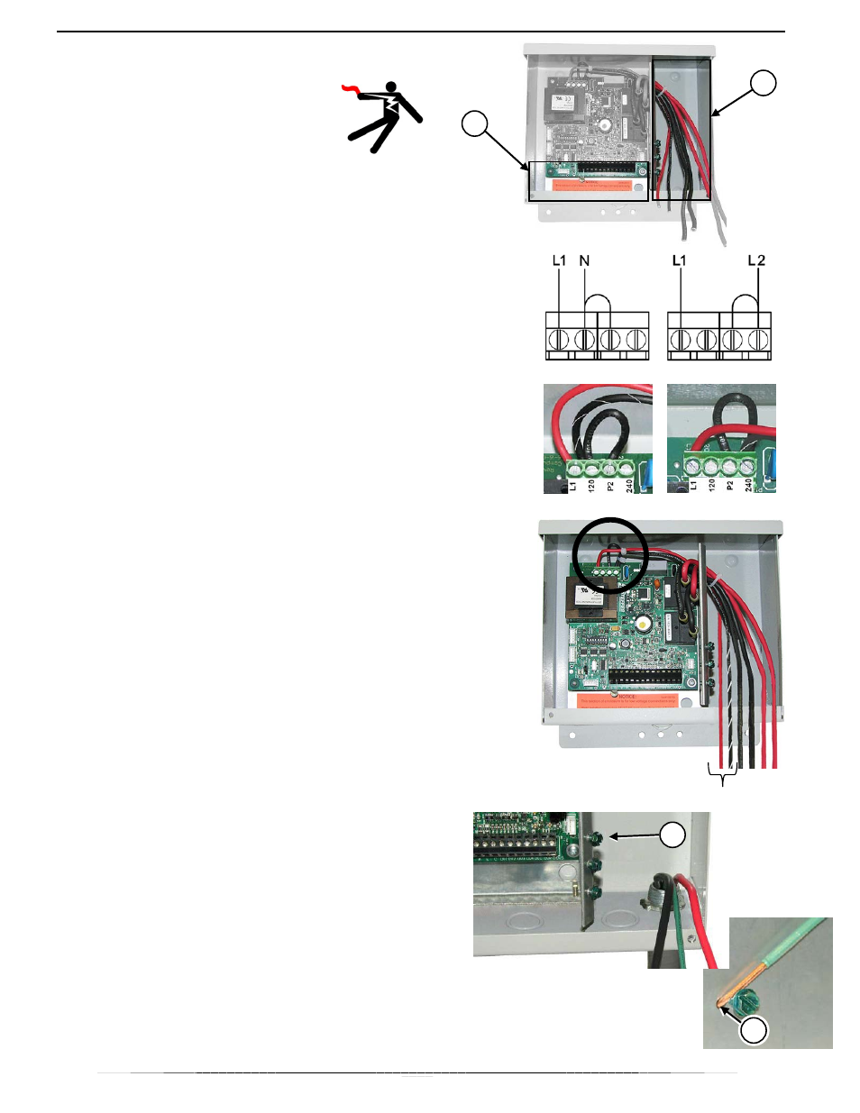
Line Voltage Connections 2-Pole
WARNING:
Hazardous Voltage. Can cause
injury or death.
Route line-voltage conductors
(circuit board power and
controlled-load circuits) and make line-
voltage connections only in the line-voltage
connection area, (1).
Use only copper conductors that are rated
for 75° C minimum.
Route low-voltage conductors (remote
outdoor sensor, power company
signal/control switch, override switch, etc.)
only into the low-voltage connection area,
(2).
Install in accordance with applicable local,
state, and national codes and regulations.
1.
The transceiver can be powered with 120 VAC or
208/240 VAC. Before connecting power to the
transceiver, the circuit board MUST be tapped for
the appropriate input voltage as shown.
NOTE: 208VAC/240VAC is factory default.
2.
Route line voltage wiring to the transceiver and
connect to the two 16 AWG wires coming from the
circuit board.
NOTE: For 120VAC power, connect the neutral
wire to L1 and connect the hot wire to
L2.
SecureGround™ Ground Bond
NOTE: This transceiver has SecureGround™
ground wire bond points. Use this
procedure to connect line-voltage
ground wires to the enclosure
throughout this installation instruction.
1.
If used, connect ground wire to SecureGround™
screw by inserting the end of the wire into
SecureGround™ anchor hole, (2).
NOTE: This connection accepts 14 to 10 AWG
solid conductor only.
2.
Hold wire firmly and bend it clockwise, 350º
around screw shank as shown.
IMPORTANT: Make sure no insulation is
between wire and screw head.
3.
Tighten screw securely.
2
2
1
120VAC
240VAC
1