Transceiver relay connections 2-pole (optional), Transceiver relay connections 5-pole (optional) – Steffes Transceiver User Manual
Page 15
12
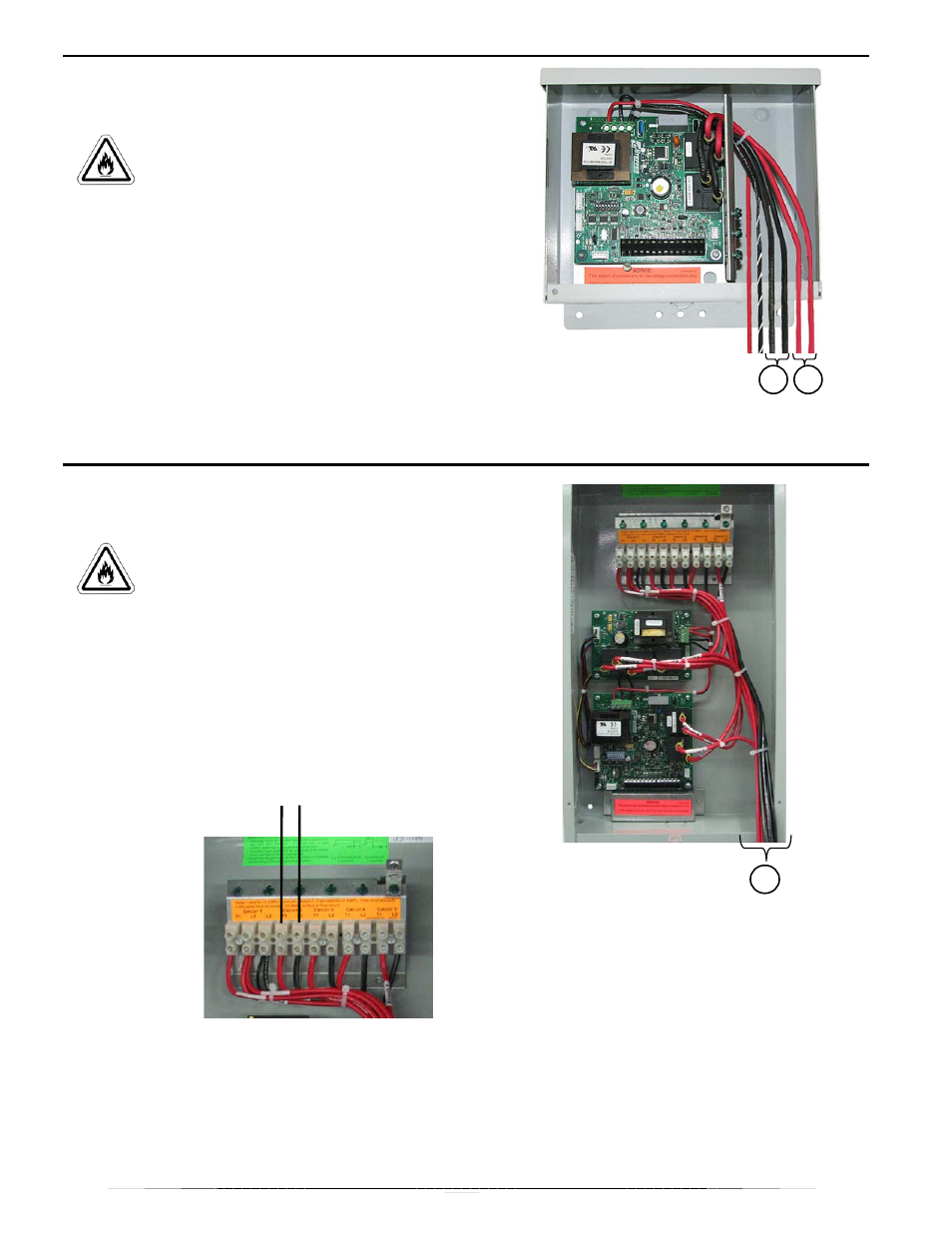
Transceiver Relay Connections 2-Pole
(Optional)
CAUTION:
Risk of fire. Can cause
personal injury or death. Use only copper
conductors that are rated at 75° C.`
minimum.
1.
If any transceiver relay(s) are NOT being used
to control other loads, insulate the ends of the
unused wires.
2.
If the transceiver relay(s) are being used to control
other loads, one leg of the circuit going to the
controlled load will be broken through the relay.
3.
To use controlled-load Relay #1, use the red relay
wires, (1). To use controlled-load Relay #2, use
the black relay wires, (2).
NOTE: Refer to the Relay Operation section of
the manual for more information.
Transceiver Relay Connections 5-Pole
(Optional)
CAUTION:
Risk of fire. Can cause
personal injury or death. Use only copper
conductors that are rated at 75° C.`
minimum.
1.
Controlled loads will be connected to the T1 and
L2 terminals for the desired Circuit # as shown
below.
2.
Locate the red and black wires at the bottom of
the transceiver, (1), for that Circuit # and route
them to the service entrance panel. Connect these
wires to an appropriate circuit breaker in the
panel.
NOTE: Refer to the Relay Operation
section of the manual for more
information.
2
1
T1 L2
1
Transceivers with time clocks
installed are not allowed to have
external loads connected to the
relays. Doing so is a violation of
the Transceiver’s UL Listing.