Heater – Steffes 1003 User Manual
Page 18
TYPICAL SYSTEM
TYPICAL SYSTEM
TYPICAL SYSTEM
TYPICAL SYSTEM
TYPICAL SYSTEM WIRING DIA
WIRING DIA
WIRING DIA
WIRING DIA
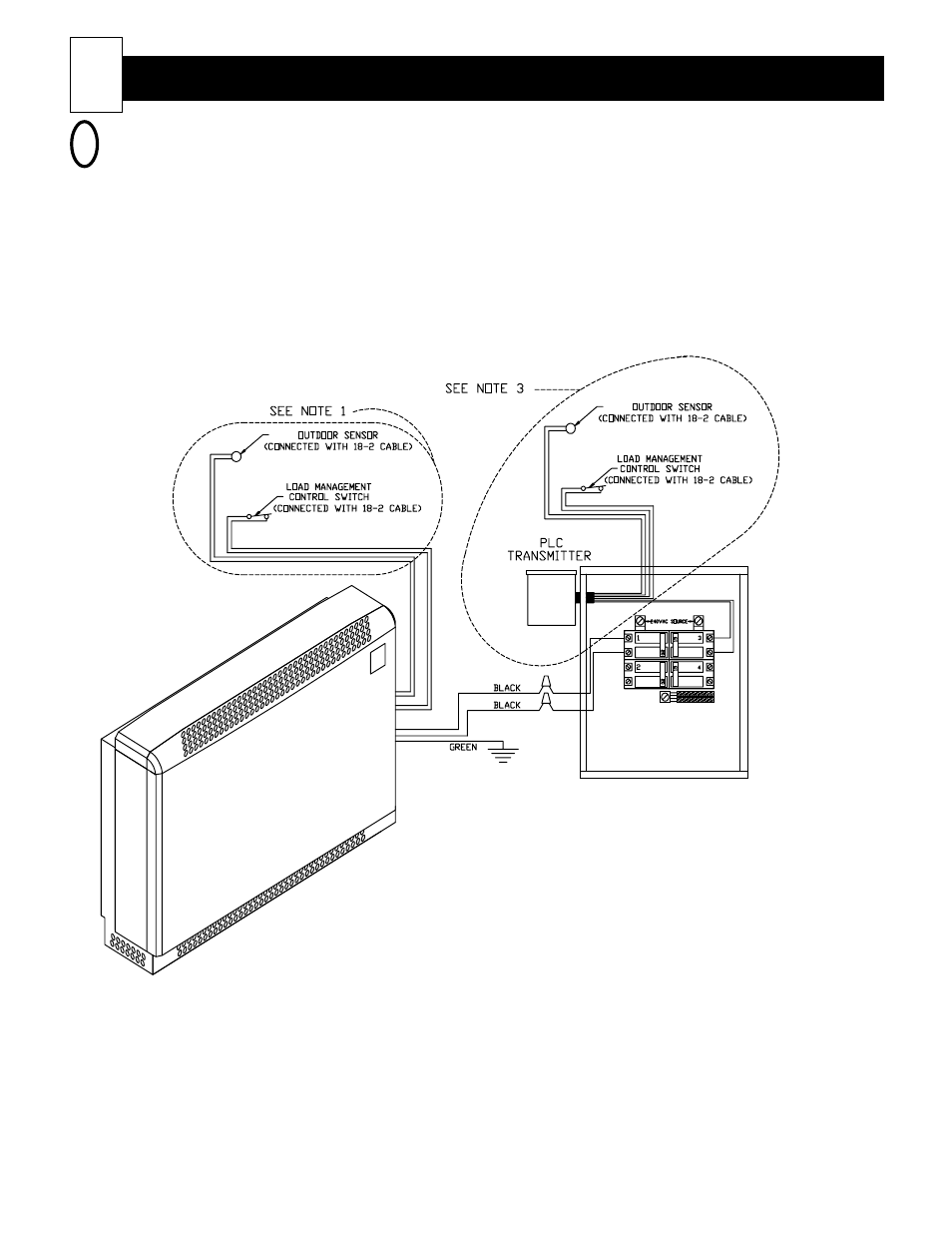
WIRING DIAGRAM
GRAM
GRAM
GRAM
GRAM
Connections shown are for 230 VAC heaters. Refer to the Unit Identification Label on the lower
right side of room heating unit for the heating element voltage of your heater.
4
Heater
Heater
Heater
Heater
Heater W
W
W
W
Wiring
iring
iring
iring
iring
(cont'd)
(cont'd)
(cont'd)
(cont'd)
(cont'd)
17
Note 1:
Do not make these connections if using the Steffes Power
Line Carrier (PLC) control system to control the heater(s) in
the installation. The outdoor sensor is an optional feature.
(Order item #1302026.)
Note 2:
The Steffes Power Line Carrier (PLC) system is an optional
heater control method. PLC control is available with the use
of the Steffes PLC Transmitter or the Steffes Comfort
Control Relay Panel (CCRP). If using the PLC Transmitter
and installing it outdoors, an outdoor sensor for automatic
brick core charge regulation is not required. If installing the
PLC Transmitter indoors or if using the PLC control system
built into the CCRP, one external outdoor sensor is required
for automatic brick core charge regulation.
FIGURE 11
NOTE