Heater wiring, Cont'd), Fan circuit charge circuit #1 charge circuit #2 – Steffes 2006 User Manual
Page 23: Controls and, Optional time clock
F1
B2
B1
R2
R1
F2
BLUE
BLUE
RED
RED
BLACK
BLACK
CHARGING
LIMIT
LIGHT
SERVICE
LIMIT
CHARGING
H
E
A
T
IN
G
E
L
E
M
E
N
T
S
B
R
Y
Y
R
F
O
O
B
DAMPER
CONTROL
RESISTOR
FAN
DAMPER BOARD
OUTPUT
BOARD
BLACK
BLACK
RED
RED
FAN
SPEED
RESISTOR
FAN CIRCUIT
CHARGE CIRCUIT #1
CHARGE CIRCUIT #2
GREEN
R
E
D
B
L
A
C
K
RELAY
ELEMENT
RELAY
FAN
NOT
CONNECTED
RELAY
ELEMENT
WHITE/BLUE
BLACK/YELLOW
120 VOLT
240 VOLT
BLUE
BLUE/WHITE
L
N
3
2
1
OPTIONAL
TIME CLOCK
A
TR
A
N
SF
O
RM
ER
A
1
3
NO
COM
NO
COM
NO
COM
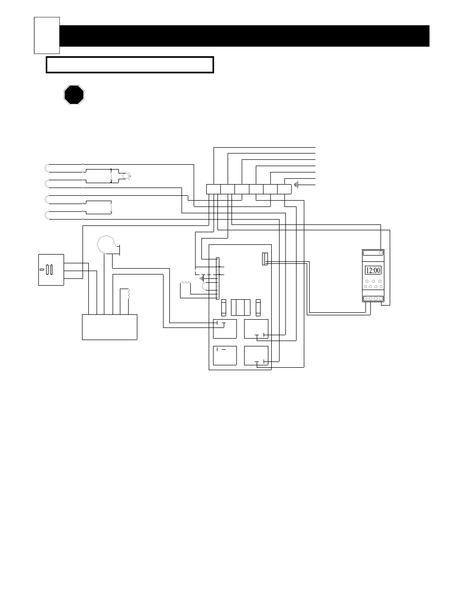
CONTROLS AND
Heater Wiring
(cont'd)
Models: 2004, 2005 & 2006 (direct wired)
Connections shown are for 230 VAC blowers. Refer to the Unit Identification Label on the
lower left side panel of the room heating unit for proper blower and heating element voltages of
your heater.
FIGURE 17
22
(See Note 1)
NOTE 1: If installing a unit configured with a 115VAC blower, and the Steffes power line carrier (PLC) control
system is being utilized, the F2 terminal block position must be the hot (ungrounded) leg.
NOTE