Heater wiring, Room heating unit identification label, Lu l u – Steffes 2006 User Manual
Page 18
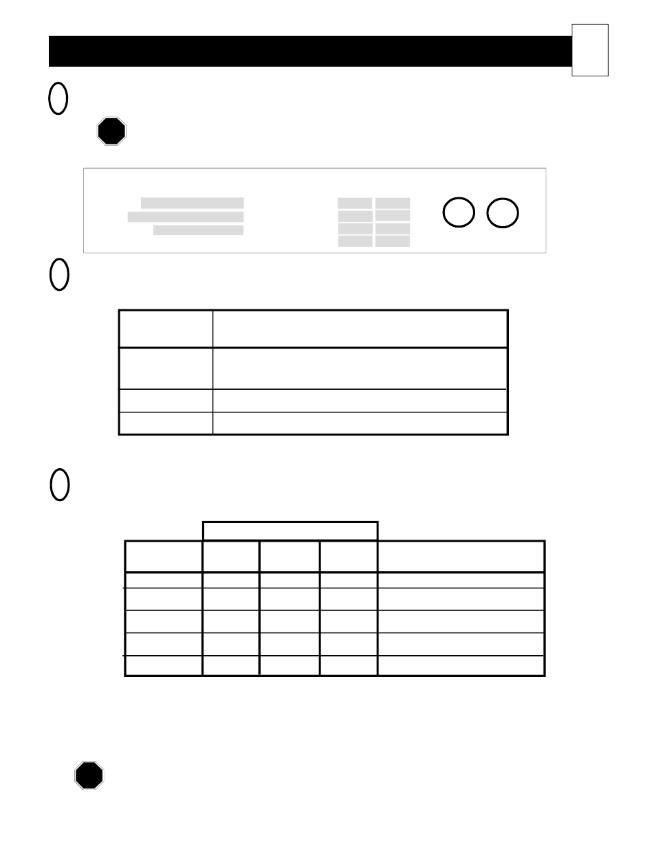
ROOM HEATING UNIT IDENTIFICATION LABEL
All heaters are UL and cUL safety listed. The listing identification label is located on the lower
left side panel of the heater.
Heater Wiring
1
17
Model
Charge Crct #1
S/N
Charge Crct #2
Options
Fan/Cntrl Crct
U.S. Patent #5.042.081
VAC
Watts
Temp Cntrl Crct
Steffes Corporation, Dickinson, ND
Manufactured in North America
Electric
Air Heater
L
U
L
U
C
LISTED
3P23
FIGURE 11
2
ROOM HEATING UNIT UMBILICAL CORD
(WIRING HARNESS) COLOR CODE
TABLE 1
WIRE COLOR
CIRCUIT DESCRIPTION
Black
Models 2002 & 2003: All heating elements.
Models 2004, 2005, & 2006: Upper heating elements.
Red
Models 2004, 2005, & 2006: Lower heating elements.
Blue
Blower and control circuit.
Refer to the Unit Identification Label on the lower left side of room heating unit
for proper blower and heating element voltages. (See Figure 11.)
Disclaimer:
The field connection wire and breaker size guide reflects only the code interpretation of Steffes
Corporation. It is the responsibility of the installer to follow all applicable codes and regulations for
the installation.
Models 2004, 2005, and 2006 units are equipped with a two-circuit element feed option. If dual feed is used,
refer to the Unit Identification Label located on the left side panel for proper sizing of each circuit. (See Figure
11.) If single-feed connection is used, size circuit for total wattage. (Charge Circuit #1 + Charge Circuit
#2 = Total Wattage.)
3
FIELD CONNECTION WIRE AND CIRCUIT BREAKER
SIZING GUIDE
#14 AWG
2.8
3.3
2.4
15
#12 AWG
3.8
4.4
3.3
20
#10 AWG
5.7
6.6
4.9
30
#8 AWG
7.6
8.8
6.6
40
#6 AWG
11.5
13.2
9.9
60
MAXIMUM CIRCUIT
WIRE SIZE
240VAC
277VAC
208VAC
BREAKER SIZE (240V Only)
Use copper wire rated at 75
o
C minimum only.
MAXIMUM kW
TABLE 2
NOTE
NOTE