Installing the heater – Steffes 2006 User Manual
Page 12
Once the proper circuits are wired to the room heating unit, install a field connection junction box. This
junction box must be large enough to conform to all applicable electrical codes and regulations. The junction
box can be installed behind the heater or mounted in the floor below the heater. If a location below the floor
is chosen, the box must remain accessible for future service to the room heating unit. If a location behind
the heater is chosen, the box should remain as near the floor as practical.
A panel label is provided in the hardware package to identify the branch circuits feeding the room heating
unit.
IMPORTANT:
This label must be applied in the electrical panel and circuits must be identified.
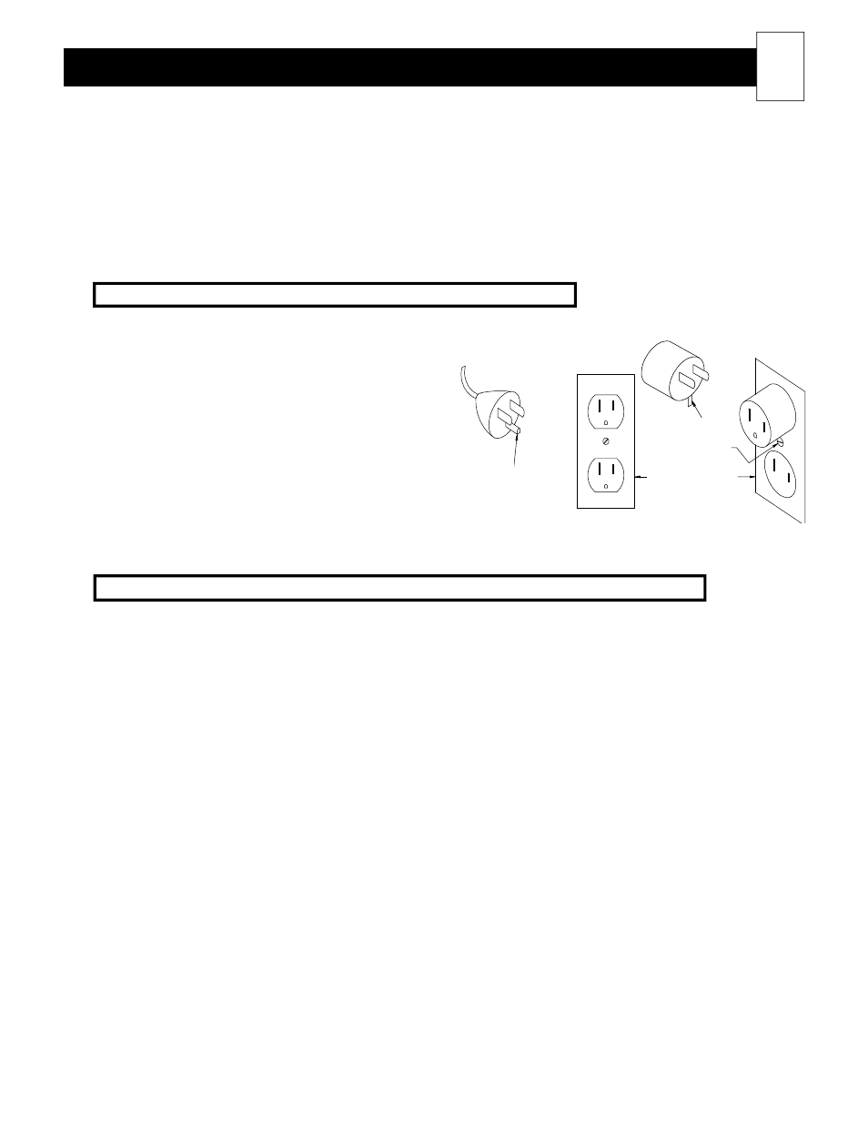
Line voltage connections for cord connected, plug-in room heating units
120V cord connected room heating units must only be
used with receptacles that are of the grounding
type and suitable for the load of the heater. See the
Unit Identification Label on the lower left side panel of
the heater to determine correct circuit size. (See Figure
7 for cord and receptacle requirements.)
The room heater's cord has a plug as shown in
Figure 7A. An adapter, as shown in Figure 7B, is
available for connecting three-blade grounding type
plugs to two-slot receptacles. The green grounding
means extending from the adapator
must be connected to a permanent ground, such as a proprerly grounded outlet box as shown in Figure 7C. This
adaptor should not be used if a three-slot grounded receptacle is available.
Heating element (brick core charging) control wiring connections for all room heating units
The heating elements in the heater are capable of being controlled on-peak (not able to store heat in the brick
core) via low voltage wiring, line voltage wiring, with a wireless power line carrier signal, or with a time clock.
The power line carrier transmitter and time clock are optional control devices. If either of these methods of
control are desired, they must be specified at the time of order to be included with the heater shipment.
If using low voltage control, all connections to the room heating unit
’s control circuit must be routed through the
low voltage raceway using the factory installed wiring. Class II (low voltage) wiring should never enter a line
voltage area of the heater, including its umbilical cord, unless it is rated for line voltage. (See Figures 13 and 14.)
If a power line carrier transmitter is being used for peak control of the room heating unit, low voltage connections
are not necessary. The transmitter can be mounted indoor or outdoor. It will transmit the peak control signal
through the entire power line system in the building. In addition to providing peak control information, it will
also transmit outdoor temperature information for automatic brick core charging. Installation instructions for this
method of control are provided with the Steffes power line carrier control system.
If using a time clock for peak control of the heater, the time clock is connected to the heater via low voltage
wiring. An installation instruction sheet is included with the time clock. Please refer to these instructions for
installation of this device inside the heater.
If line voltage control is utilized, an external switching device (such as a relay panel) is necessary to directly
control the heating element charging circuit. If relying on this method of control, the face plate on the heater will
continuously display a brick core operating mode of
“C” (charge) regardless of whether it is an off-peak or on-
peak time. It is suggested that the installer change the heater so that current room temperature followed by an
“F” (Fahrenheit) or “C” (Celsius) is displayed. This is done by adjusting the data in Location 14 (L14) to d01,
or a peak control sequencer can be installed to correct the brick core operating mode display. (Order item
#1309006.)
Installing The Heater
(cont'd)
11
FIGURE 7
adapter
g ro unding
grounding screw
grounded outlet
box
g ro unding