Power-on tri-state (bluestorm/sp models only), Connectors and pinouts – Connect Tech BLUESTORM UNIVERSAL PCI CTIM-00015 User Manual
Page 13
BlueStorm Installation Guide, Connect Tech Inc.
Revision 0.08
13
Note that Auto 485 is a single jumper. The second site is not in use. See
for the location of this jumper.
Power-On Tri-state (BlueStorm/SP models only, excludes
BlueStorm/SP RJ-11)
BlueStorm/SP models offer a power-on tri-state similar to the Auto-485 mode listed above. The
BlueStorm/SP implementation will tri-state ports configured as RS-485 full duplex. This is
meant to ensure compatibility with our legacy Blue Heat/PCI cards.
Jumper J1 controls the power-on tri-state functionality. Install a jumper on the first location of
the J1 in order to tri-state Port 1 at power-on, install a jumper on the second position for Port 2,
etc. Ports will not come out of tri-state until the driver opens the affected port.
modes require you to select the appropriate
mode via software. Please refer to the
readme.txt
files found in the appropriate
directories on the BlueStorm/LP/SP/SP Opto CD.
Connectors and Pinouts
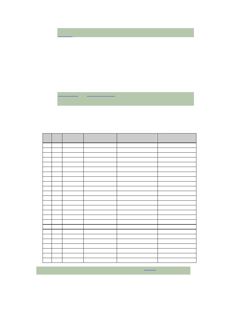
Table 1: DB-25 Female Pinouts for BlueStorm/LP (2 port connector)
Pin
No.
Port
No.
RS-232
Signal
Signal
Direction
RS-422/485
Signal
Signal
Direction
1
2
SG
signal gnd.
SR
signal ref.
2
1
TXD
output
TXD-
output
3
1
RXD
input
TXD+
output
4
1
RTS
output
RTS-
output
5
1
CTS
input
RTS+
output
6
1
DSR
input
CTS-
input
7
1
SG
signal gnd.
SR
signal ref.
8
1
DCD
input
RXD+
input
9
2
TXD
output
TXD-
output
10
2
RXD
input
TXD+
output
11
2
RTS
output
RTS-
output
12
2
CTS
input
RTS+
output
13
2
DSR
input
CTS-
input
14
NC
no connect
NC
no connect
15
NC
no connect
NC
no connect
16
NC
no connect
NC
no connect
17
NC
no connect
NC
no connect
18
NC
no connect
NC
no connect
19
2
DTR
output
RXD-
input
20
1
DTR
output
RXD-
input
21
NC
no connect
NC
no connect
22
1
RI
input
CTS+
input
23
2
RI
input
CTS+
input
24
NC
no connect
NC
no connect
25
2
DCD
input
RXD+
input
Cable CBG002 sends the signals to two DB-9 male connectors. See
NOTE: This is not the pinout of DB-25 cable CBG007.