B. cable information – Panasonic WV-7140 User Manual
Page 7
Attention! The text in this document has been recognized automatically. To view the original document, you can use the "Original mode".
B. Cable Information
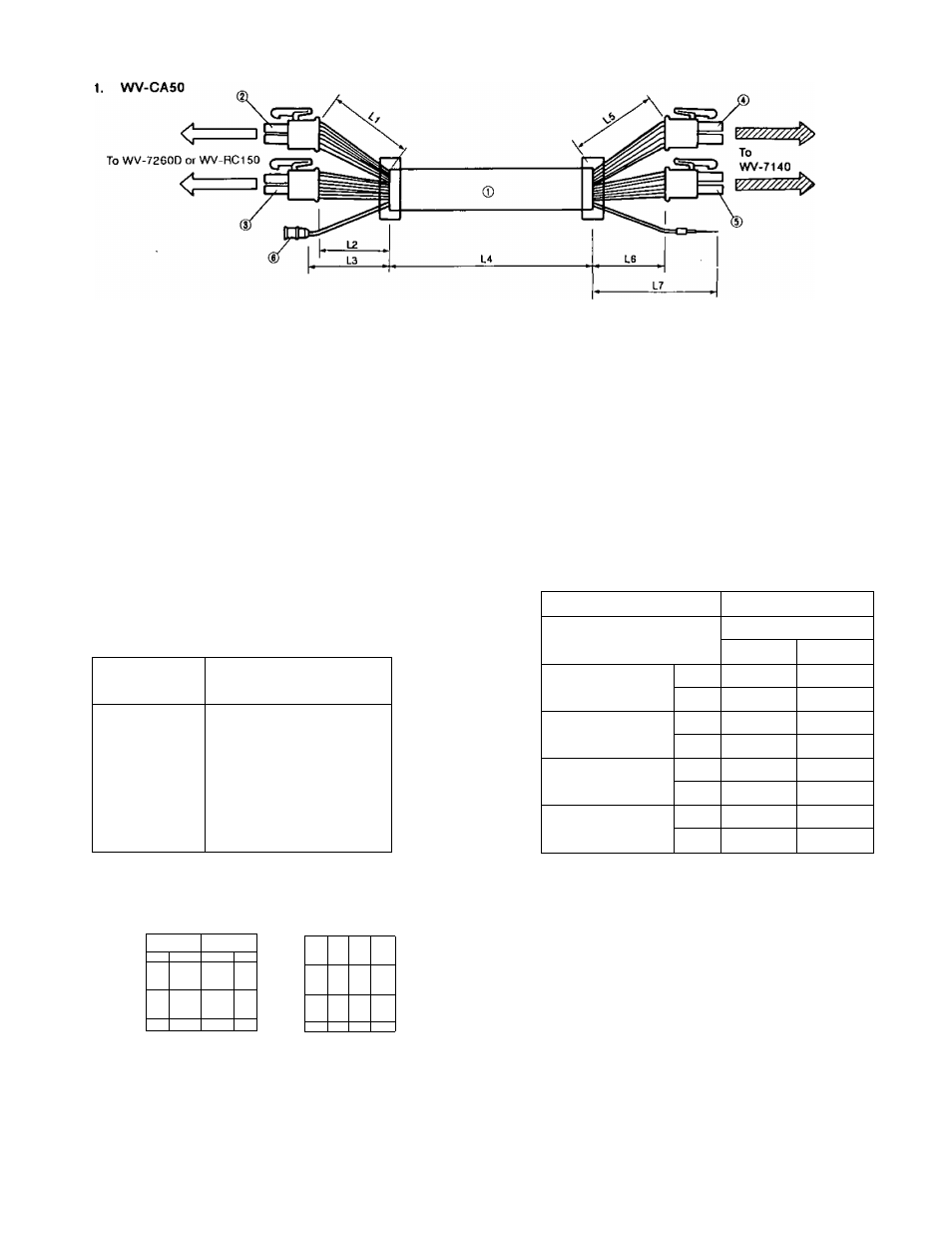
• The length of wires. (Approx.)
L1: 2-1/2’
L5:6’
L2: 2’
L3: 12"
L4: 65’
L6: 6*
L7:
V
Parts name
1
.
2
.
3.
4.
5.
6
.
18 wires cable
14 pin connector
12 pin connector
10 pin connector
8 pin connector
BNC connector
2. In case of using the accesory connectors
(MX5557P08 and MX5557P10)
Select a multi-conductor cable which meets FR-1 rating
with 8 or 11 wires cables for WV-7140. A 11 wires cable is
used to extend the cable length.
Connect the 8 or 11 wires cable to the following position of
the accessory connectors.
CN Pin No.
WV-7140
Usage of Terminal
CN2-1
CN2-2(3)
CN2-5(6)(7)
CN1-7
CN1-8
CN1-9
CN1-10
CN2-8
24V AC CAMERA
FAN HEATER
AC COMMON
DCCOMMON
IRIS CONTROL
FOCUS CONTROL
ZOOM CONTROL
GND
• The length of the cable is determined by the chart
below. {The system should be operated by 24V AC and
the power consumption should have less than 11W for
the camera, 44W for WV-7141.)
Model
WV-7140
Copper wire gauge /WG No.
Number of Conductors
8 wires
11 wires
#24
ft
26
60
m
6
15
#22
ft
40
05
m
10
25
#20
ft
60
150
m
15
45
#18
ft
100
250
m
30
70
• If 11 wires cable are available for WV-7140 connect
the remained 3 wires to the { ) position.
”1
lO
9 £
i 7
6
5
4 :
) 2
1
CN1
8
7
6
5
4
3
2
1
CN2
The accessory connectors view from wiring side.
•
The above lengths are approximate.
•
When the camera housing is mounted on the Pan/Tilt
Head WV-7260D, refer to the operating instructions of
it.
CAUTION:
CONNECT TO 24V AC CLASS 2 SUPPLY ONLY.
Caution:
To prevent fire or shock hazard,
the UL listed wire VW-1, style 1007
should be used for the cable for AC
24V Input Terminal.
- 6 -