Installation of camera, Applicable cameras and lenses, Preparation of wiring – Panasonic WV-7140 User Manual
Page 5
Attention! The text in this document has been recognized automatically. To view the original document, you can use the "Original mode".
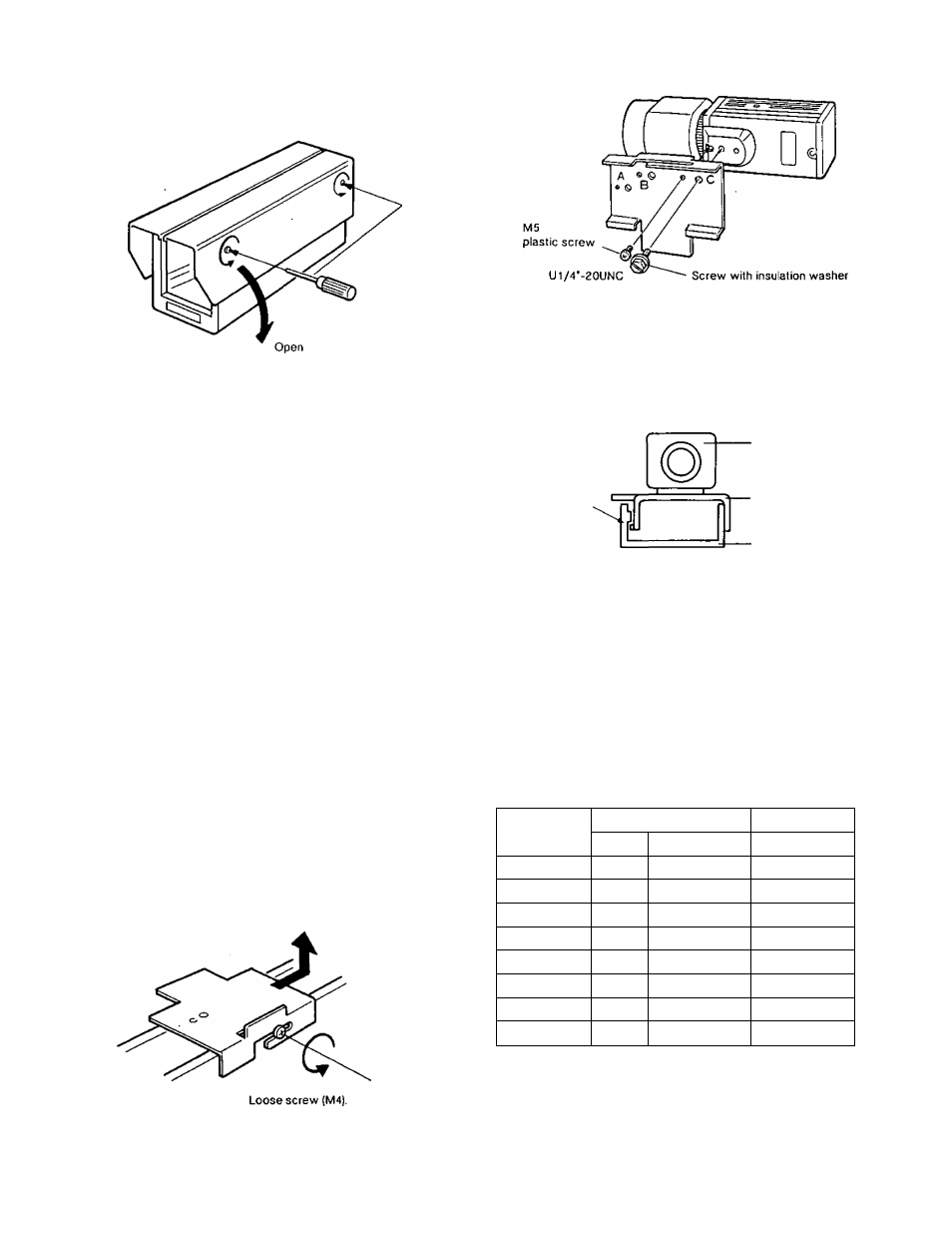
1. Open the side cover with the flat head screw driver.
PREPARATION OF WIRING
2. Decide the wiring hole size for the rubber bushing, then
cut the bushing at the appropriate size. The minimum
hole size is 13/16 (20 mm).
To the terminal strip
Cut here —
if necessary
Min. Inner Diameter
013/16" (020)
L
Bushing
REAR
Multi-conductor
cable and coax, cable
from Pan/Ti!t Head or
custom made remote controller.
2. Fix the camera mounting plate on the bottom of the
camera using two screws.
M5 (plastic screw) is used as a stopper for the camera
from rotating except WV-BL90, WV-CL110.
This position should be changed by selection of the
camera and lens.
A: Cameras used with a fixed focus lens.
B: WV-BL90/WV-CL110 with WV-LZ81 /6 lens.
C; Cameras with WV-LZ81/6 tens.
Make sure
this position
to be fixed.
CAUTION:
Camera
Camera Mounting
Plate
Chassis
Mount the camera (with mounting plate) on this
unit carefully.
When the camera LED reflects on the glass and
the light comes in the screen, stick the Power
Indicator Masking Label (accessory) on the LED.
Pass the cables through the wiring hole.
INSTALLATION OF CAMERA
1. Loose M4 screw to remove the camera mounting plate.
APPLICABLE CAMERAS AND
LENSES
The recomended combination of the Panasonic camera and
lens to WV-7140 is shown in the following table.
Lens
for 1/2' camera
for 2/3' camera
Camera
Fixed
WV-L201/6
Fixed
WV-CD24
-
-
o
WV-BD404
-
-
o
WV-BL204
•
0
•
WV-CL304
0
0
0
WV-BL604
o
0
o
WV-CL704
0
0
o
WV-BL90
•
•
X
WV-CL110
•
•
X
x: Inhibited combination in size
o: Recommended combination in size
•: Possible combination but remains much space inside
of housing.
Caution:
The Fan/Heater unit (WV-7141) should be required in
consideration of the ambient operating temperature
with the camera and the lens.
- 4 -